Since I swapped out the U39 op-amp, the pins for left channel and right channel (5,10) on the Cem3360 (U44) are only getting + 0.4Vdc now. Before I did the swap they were +2 Vcd. I wonder what this means. Kinda makes me think this new op-amp on U39 is not playing nicely. I should probably check voltages on U39 to make sure but I don’t know what I’m looking for. With maximum hindsight in effect, before I swapped U39 out, I should’ve checked voltage on U44 right after I swapped out just U30 and U32. The other pins you asked me to check on U44 have no DC voltage present.
Side note, I’m looking at the AS3360 clone of the CEM3360. Has anyone tried these on Ensoniq keyboards?
Well this is getting strange. Maybe time for a review.
Did you re-check power supply voltages after the capacitors were replaced
Did you order the replacement chips from Mouser and do you have spares.
What part number was on the original chip at position U39.
When you tested pin 5 and 10 on U44(CEM3360) was the volume slider all the way up.
Check supply voltages on the chips.
U39 TL084 pin 4 +12vdc
pin 11 -12vdc
One more item i’d like you to check.
There is a power transistor to the left of U39 covered in heat shrink. Can you tell me what the voltages are on all 3 pins.
Thanks.
If the display is working and the keyboard is making sound (albeit low sound) and changing programs, the power supply is almost certainly good. I would suspect a bad op amp in the output circuitry - you’ll have to really boost the volume externally to hear it, and that will really boost noise level.
Just got home from a long work week. I’m gonna check more voltages tonight. I swapped out the U39 op-amp at the output stage for the TI 595-TL084CN. Made the keyboard very very loud but would only play a few notes before the sound cut out completely. It sounded like it was overloading the output stage. I can power cycle and recreate this distortion. After this I checked the VCA CEM3360 and was getting very low voltages (+0.4Vdc instead of +2Vdc). Before I swapped U39 op amp, I was getting the appropriate voltage on the CEM3360. Everything on the keyboard worked fine before this (besides the low noisy output) except now it doesn’t since I swapped U39. I’ll report back late tonight.
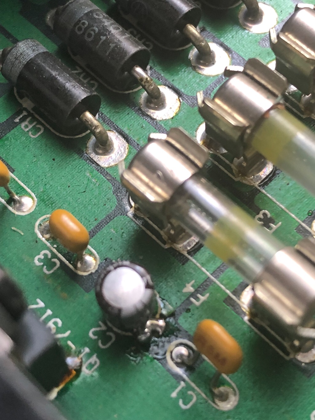
I have a short stories worth of notes regarding tonight but I discovered I have a bad lifted pad on the top side of the power supply board from desoldering one of the very small radial capacitors (C2 to be exact) that I replaced, so I need to do a full check of my solder connections before I continue to avoid any confusion or misinformation. The board looks like the traces are on both sides so I need to check all top and bottom solder connections and make corrections before moving forward. Its been awhile since I’ve done this work and the first few were sloppy to say the least.
I’m at least getting the same voltages from the power supply as I was when the unit first came into my possession but the fact that +V unreg (1.8Vdc above max) and Vbb (10Vdc above max) pins are above their acceptable voltages for the synth is still concerning to me. I did mention this in one of my first replies but moved on to other tests without addressing this issue, I think because I mentioned it was an unloaded test of the power supply. However I read off the service manual, the voltages should be the same loaded or unloaded so I think there is still an issue with the power supply. Maybe the pad to that capacitor was always bad?? Voltage regulator Outputs on the power supply are in range but the two 7805 regulators (Q3 and Q4) are showing 12.8Vdc on their Input pins which is the same value for “+V unreg” so I think the two are related. +V unreg should be no more than 11Vdc. Not sure what to think of the 10Vdc disparity coming from Vbb. Super tired off to bed and going to add some solder, fix a trace and do some more testing tomorrow. I’ll post answers to the questions you have tomorrow but to answer one of them, the original U39 op amp chip was NEC uPC4084C. I believe this is the schematic http://pdf.dzsc.com/88889/44367.pdf. Maybe its time to get that ESR meter and also check the tiny yellowish capacitors?
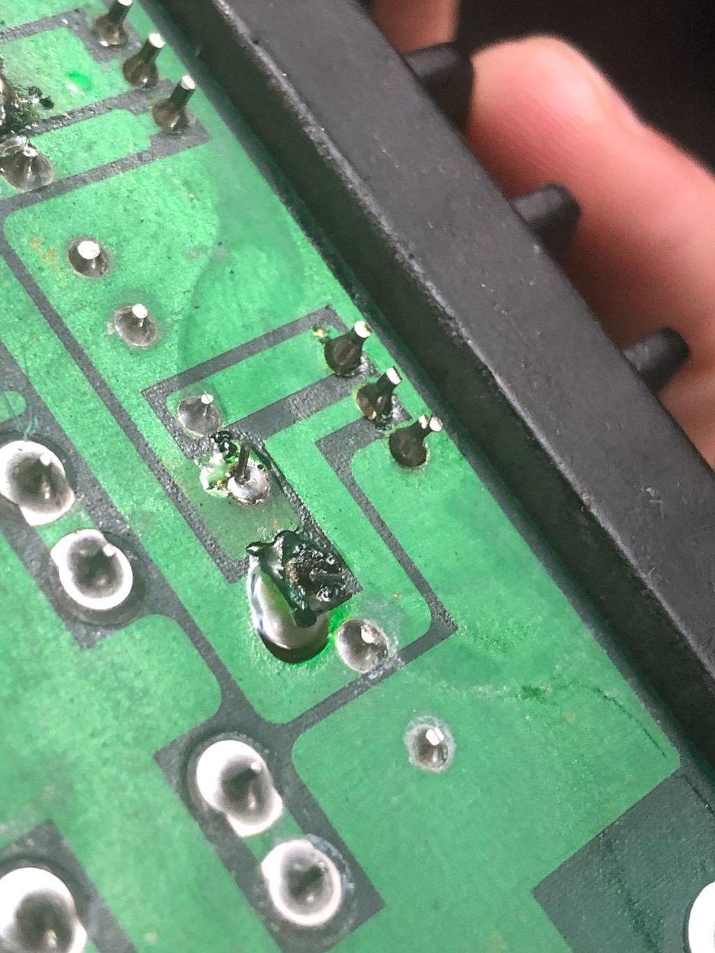
Trying to fix this trace for C2 on the power supply board. Unfortunately, the solder isn’t adhering. There is a black square on the underside of the PCB. Do you know if I have to skim the mask off on the underside to fix this? Or is it going to the top side of the board? I have ribbon cable to bridge if needed. I don’t see the schematic for the PS from Butchy’s files.
You can skim the green solder mask to expose fresh copper. I would just use a jumper wire.
That capacitor is for the -12Vdc supply.
The hand drawn schematics from Butchy’s site are from the metal version of the ESQ-1.
I have been tracing the audio path to another op-amp on the main board. It’s located near U32 and is a 14 pin chip. Part number on my unit is MC34085 (U31). I’ve found that the schematics for the SQ80 are very similar to the ESQ-1. At least in the output section.
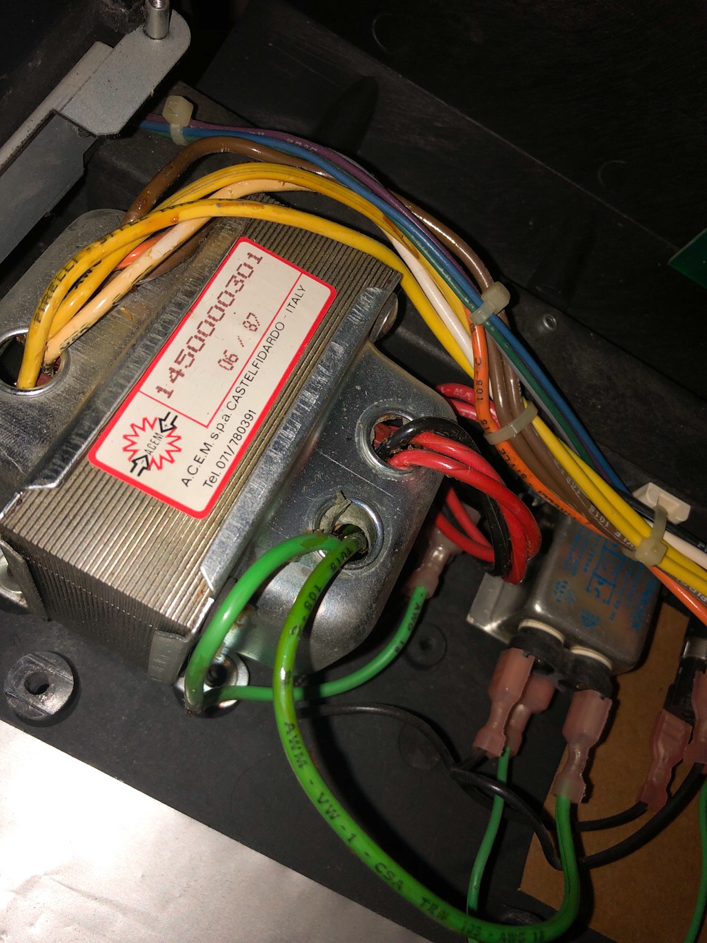
Regarding the elevated voltage levels - i can only guess that maybe the unit is being fed from a higher voltage from the wall outlet. Double check to see the top of the transformer - should have a label with the voltage supply rating on it. Also take a reading of the voltage at the wall socket. Can you also tell me what the secondary AC readings are on the power transformer.
Unfortunately the transformer doesn’t list its rating. I checked the wall outlet and was getting 119Vac and on the transformer I checked the pins for digital supply and analog supply without the PS board connected and both were in range like normal. Is that what you mean by secondary AC readings? Gonna need a little more time with this. Reason being is because a few days ago when I was voltage checking, I heard a faint noise and didn’t think much of it until I started to smell something. I immediately turned it off. It was the U39 op amp smelling that I replaced. This was during the time when I was getting a very loud and distorted output. That was the first time I had the unit on for a few minutes after replacing that op amp. Was a rough night and I wanted to take a step back and figure out why the power supply is over voltage on +V unreg and Vbb. I need to still check voltages for that power transistor by U39 but I want to remove U39 from the board first.
Going back to fixing the bad solder pad. Can I skim off anywhere unpopulated on the underside of the board or do I have to skim a specific trace?
You can skim off the green mask anywhere around the component terminal.
Secondary readings are the voltages from the secondary of windings of the transformer.They are connected to terminals 1 & 3, 4 & 6, and 7 & 9 on the power supply.
That transformer is the correct model for 120vac operation.
Check the solder joints under the connector from the transformer and also the diodes.
U39 is being stressed from the power supply or the signal from the VCA chip. That’s why i had you check for a DC voltage on the VCA outputs.
At this point i would remove both the VCA and op-amp (U39) and check their supply voltages after you get the power supply fixed.
Since the keyboard was still functioning after recapping the power supply (which read identical to what it was before) and was also working the same before swapping U39 out, I’m inclined to put the old op-amp back in so I can test that transistor to the left of it since the VCA was reading +2Vdc voltages fine up until swapping U39, then the VCA went down to +0.4Vdc afterwards. Hopefully the VCA will read +2Vdc again as I’m just reversing the process. Of course, I still need to figure out why the power supply board has high voltage readings and that should take precedence. All diode and transformer solder points look original, untouched and in good shape on the PS board. I plan on making another mouser order and get some spares and might as well get some diodes and regulators at this point too, who knows maybe I accidentally gave the new op-amp a little static or it’s faulty to begin with. Do you know if I’ll be able to test just the VCA voltage without U39 installed or will it not read anything? Also do you think that there’s a possibility the VCA is bad even though it was getting +2Vdc? I should’ve took your advice to add dip sockets to those op-amps… also thank you for being patient as I drag my feet around
It’s possible the replacement op-amp suffered electro-static damage.
You should be able to test VCA voltage without U39 installed. If it drops back down to 0.4vdc after
you install the chip then it may be bad.
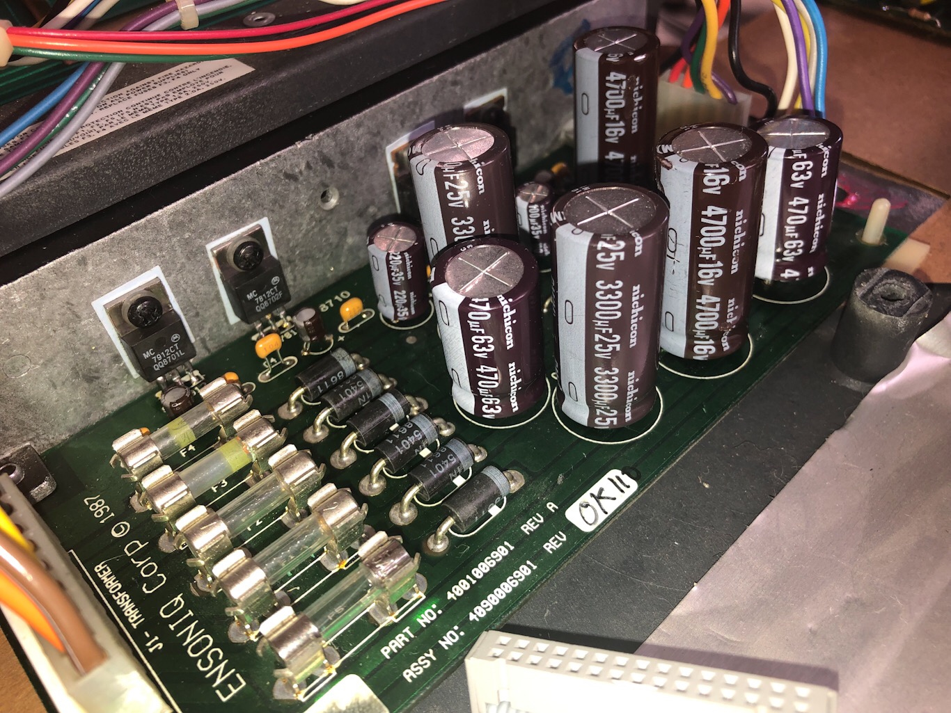
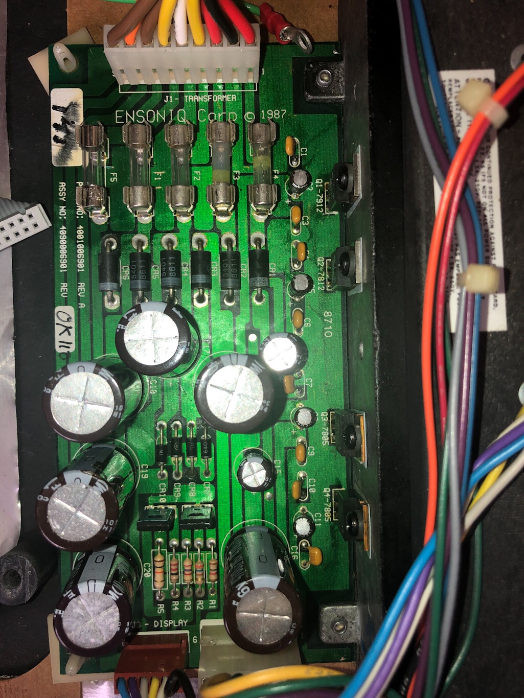
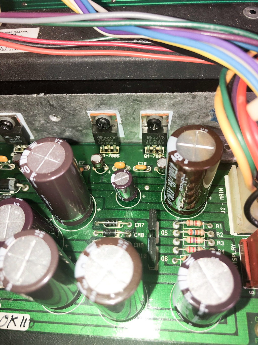
Can you take a picture of the power supply showing all components?
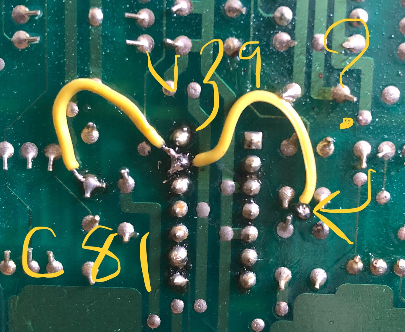
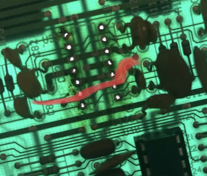
Ok I feel like I have at least some useful information to move forward. I also attached photos of the power supply. I removed the new U39, put in a dip socket and then put back the old U39. Unfortunately the same overloading occurs now on the old op amp as well. It didn’t do this before so maybe I messed up the VCA putting that replacement in?? The CEM3360 is reading +1.9Vdc on its output pins with volume slider up so I think I’m ok there. I also rechecked pins 6 to ground and pin 9 to ground and both read zero like they should. The unfortunate part about the removal of the TL084 opamp U39 was a broken trace! I followed it to C81 and was able to bridge it (one photo attached with red marking and one with the bridge in place). The pin on U39 leads from c81 to a U39 pin then goes to a small pad sandwiched between c118-121. I tested U39 after bridging the trace and am getting a solid +12Vdc on pin 4 and a solid -12Vdc on pin 11.
I tested the transistor Q7 to the left of U39 and was reading -12Vdc on the input and -5Vdc on the output. Another note, the keyboard originally would make a little blip sound powering up and down but now it’s more like a longer squeal.
Regarding the power supply, the skim job I did caused the heat sink to get crazy hot so I removed that and rechecked voltages and I’m back to normal minus the ongoing small over voltage which has been present since day one. So maybe the pad I tried to fix didn’t need fixing and the underside pad still worked.
To recap, at this point I’m not sure why the audio output is still overloading after putting back the original U39 when it was working ok before. I need to go back and check for any unwanted voltages. Thinking about ordering a Cem3360 clone and a new TL084.
If you’re ordering parts i would order a few spares of the TL084 just in case they fail due to other issues.
It always pays to keep a few spares - they’re cheap insurance.
In regards to the power supply voltages the one voltage that’s about 1.9 Vdc over should not be a concern. Other users have reported a slightly higher voltage than the chart in the repair manual.
In regards to the other voltage that is 10Vdc over - that is a concern. It feeds the display driver chips and those displays are not easy to source replacement parts.
I believe one (or both) of the power transistors on the power supply are shorted. I have a Rev C power supply which is slightly different than your Rev A supply. But they both have those power transistors which control the high voltage to the display. One transistor should be a JE172 and the other should be a JE182. Mouser sku 863-MJE172G and 863-MJE182G. I would also order a few for spares.
Are both the left and right channel outputs higher in level and distorted? What happens when the volume slider is turned down?
Pat
The reason i ask about the output levels on both channels is that the trace repair you made with the jumper wire at U39 should have affected only the left channel.
Also the transistor you checked that had -12vdc and -5vdc are correct readings.