Ok, yes, upper slider is measuring properly, 5v at the top, 2.5 halfway and 0 at the bottom. Lower slider is indeed off - only 1.87 at the top, and 1.16 at half.
Good work !!! No wonder volumes are different - that CPU chip is reading the voltages to set the respective digital value which is then evaluated by the DAC.
Now we need one of them sliders - that’ll be another problem I think.
ROLAND Part# is EWANNKX10B14 - is basically a 10kOhm Linear 30mm travel. There are lots of them available HOWEVER, at some point in time the pin arrangement on all slider pots changed to all pins at one end (which this ones are not)
Hmmm … maybe take out the board where the sliders are located and check closer - I think you should be able to see the underside like the picture below:
Maybe follow the voltages first - then turn off power, remove the connector at C103 and measure resistances across the components - use schematic snipped in previous post?
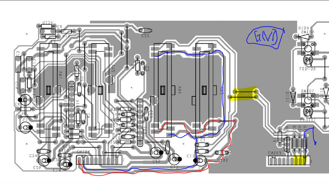
Finally had some time to disconnect the board where the sliders are located, everything matches up with the diagram you attached, but I’m wondering a couple things - is the yellow where I’m going to measure resistance and the red/blue the voltage? Or am I misreading? I’m a little stuck on where exactly to measure, and what I’m looking for as far as measurements.
Also, saw the edit and the revision with that part number, are you saying the one that you currently mentioned will work, or not? Not sure if my soldering skills will allow me to change it out myself, but if that’s the part that will fix the issue I’d like to get one, even if I need to have someone else do the swap.
No power required.
You need to measure resistances between the points - ie measure resistance from pin3 to the jumper bridge (yellow) - essentially just make sure all the tracks are showing 0 Ohm.
The red and blue lines are the path where +5VDC and GND respectively are supplied to the sliders. Hence you should be able to measure from let’s say the red line point (CN104 pin 10) to CN103 pin 3 or pin2 on CN103 and read the resistance - slider fully up = 0 Ohm and slider fully down about 5kOhm (NOTE: The two 10kOhm sliders are essentially in parallel so the readings will be not straight forward).
Maybe even take a close-up clear photo of the traces on that board to see whether traces have gone bad.