
hello ![]()
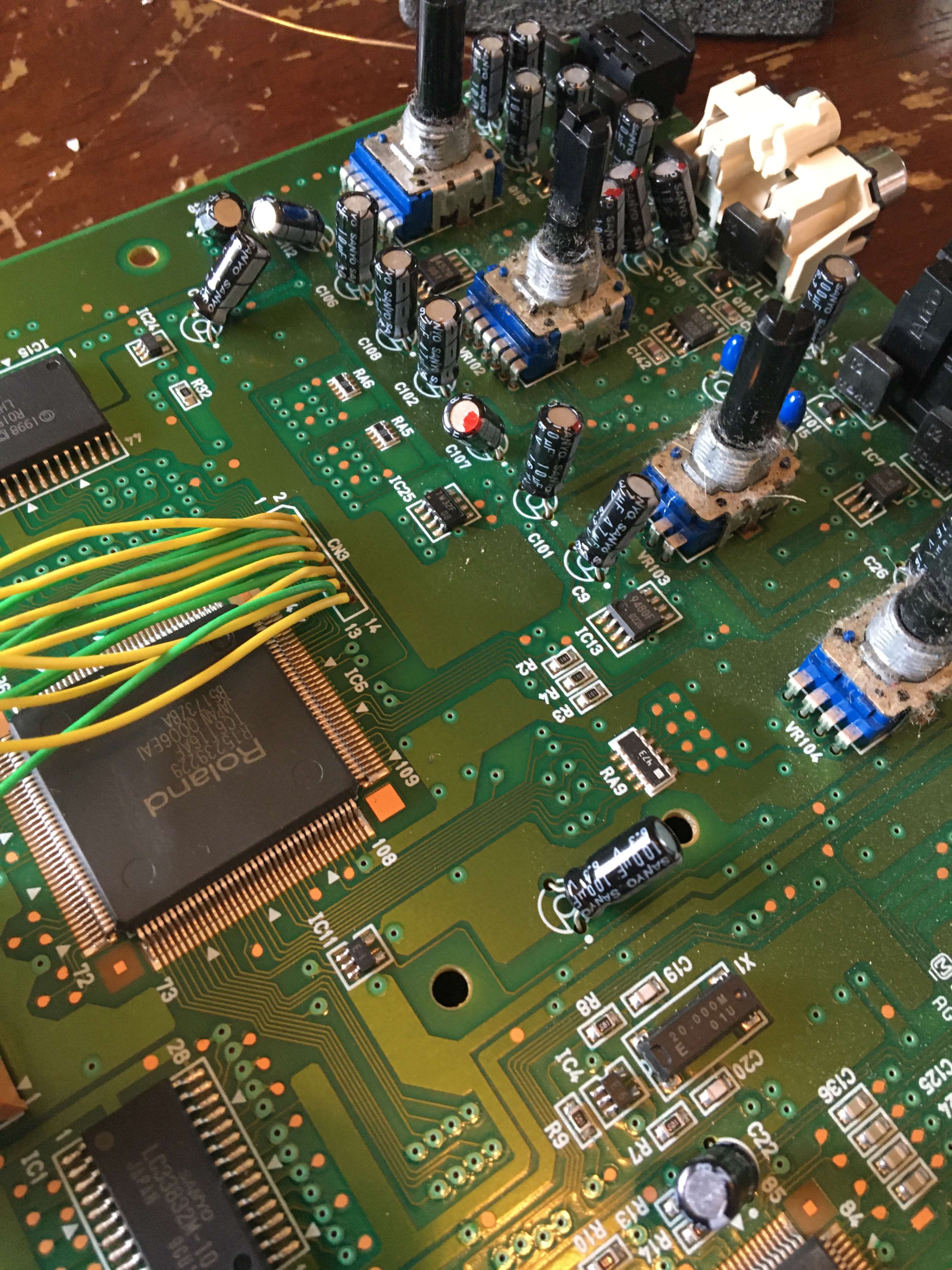
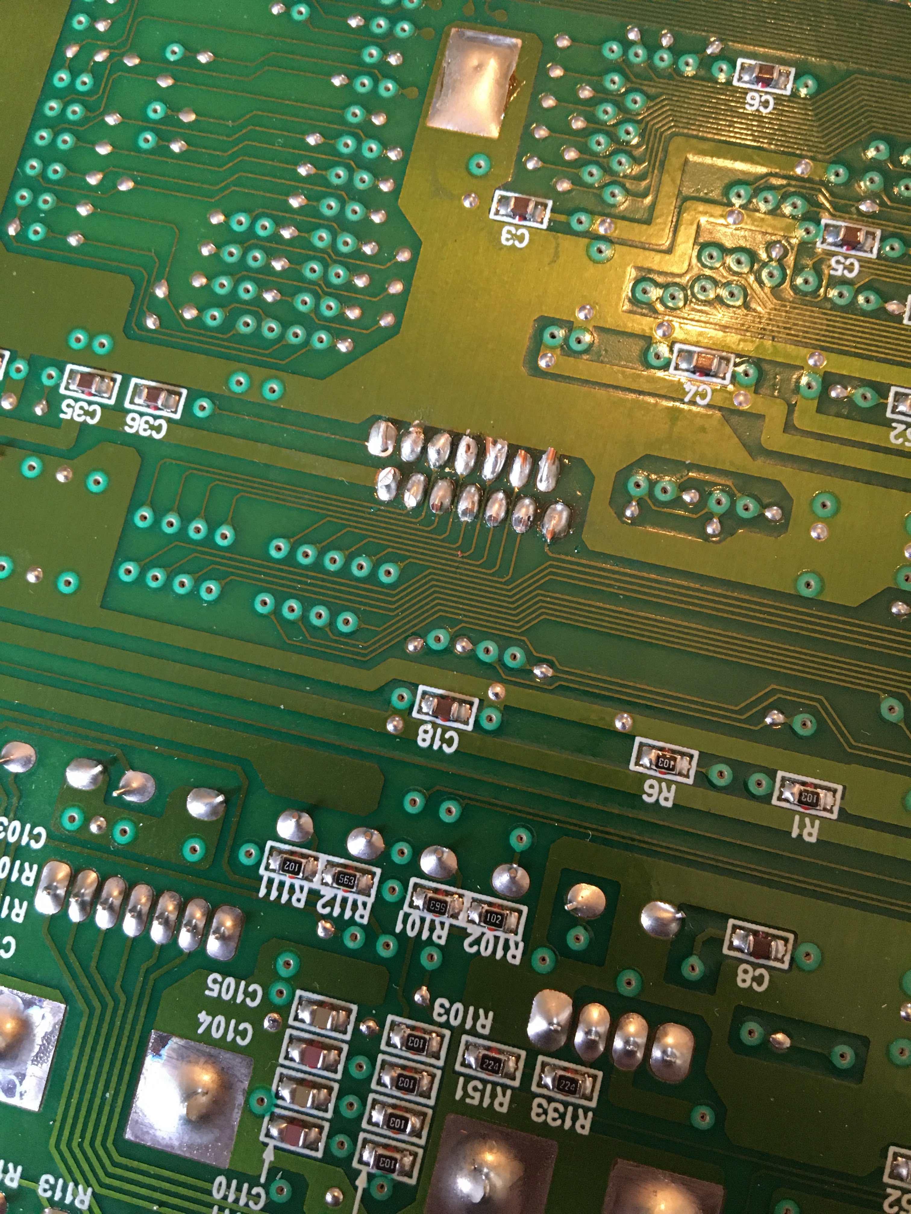
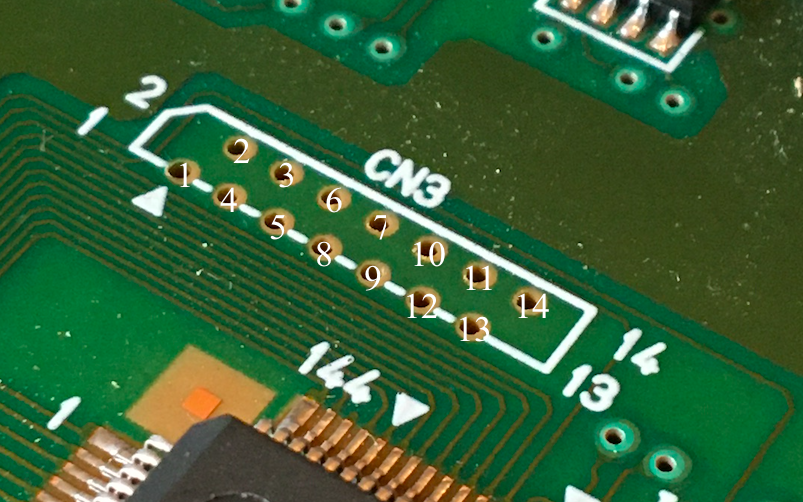
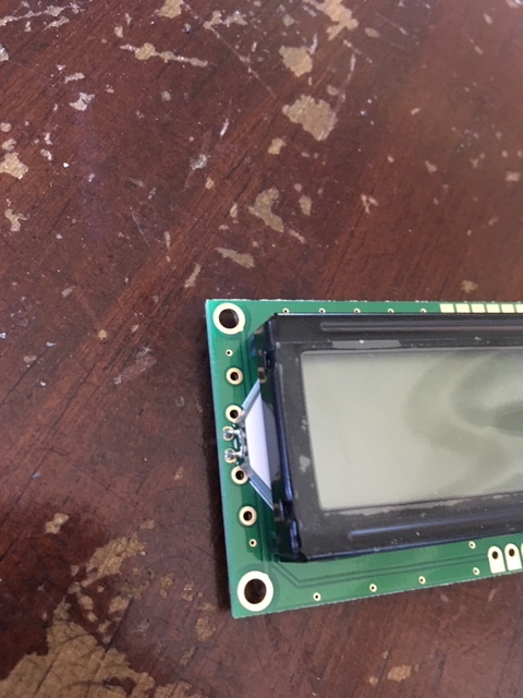
It’s the scenario 2 the right counting method. you can see on the bottom the pin 3 is going to ground plane and the pin 2 from the decoupling capacitor C36 + pin 13 to the ground plane like on the schematic.
I hope it will work ![]() I’ve got only one case where a standard LCD was not working with a Roland product. It was with a MC50 MKII.
I’ve got only one case where a standard LCD was not working with a Roland product. It was with a MC50 MKII.
after some search this could be another source:
HERE
but it will requires very high skills with fine pitch fpc. (or with 0.5mm PCB adapter)
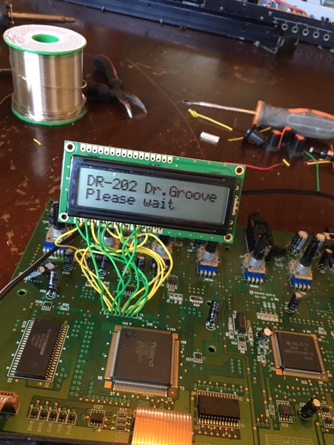
Thank you again, Genesis! Scenario 2 seems to be more logical indeed. The LCD screen you suggest looks almost like a 1 for 1 replacement…complete with ribbon cable! Very nice. I ordered some screens yesterday, so they should be arriving this week…I’ll experiment with them first and post some updates…
no problem ![]()
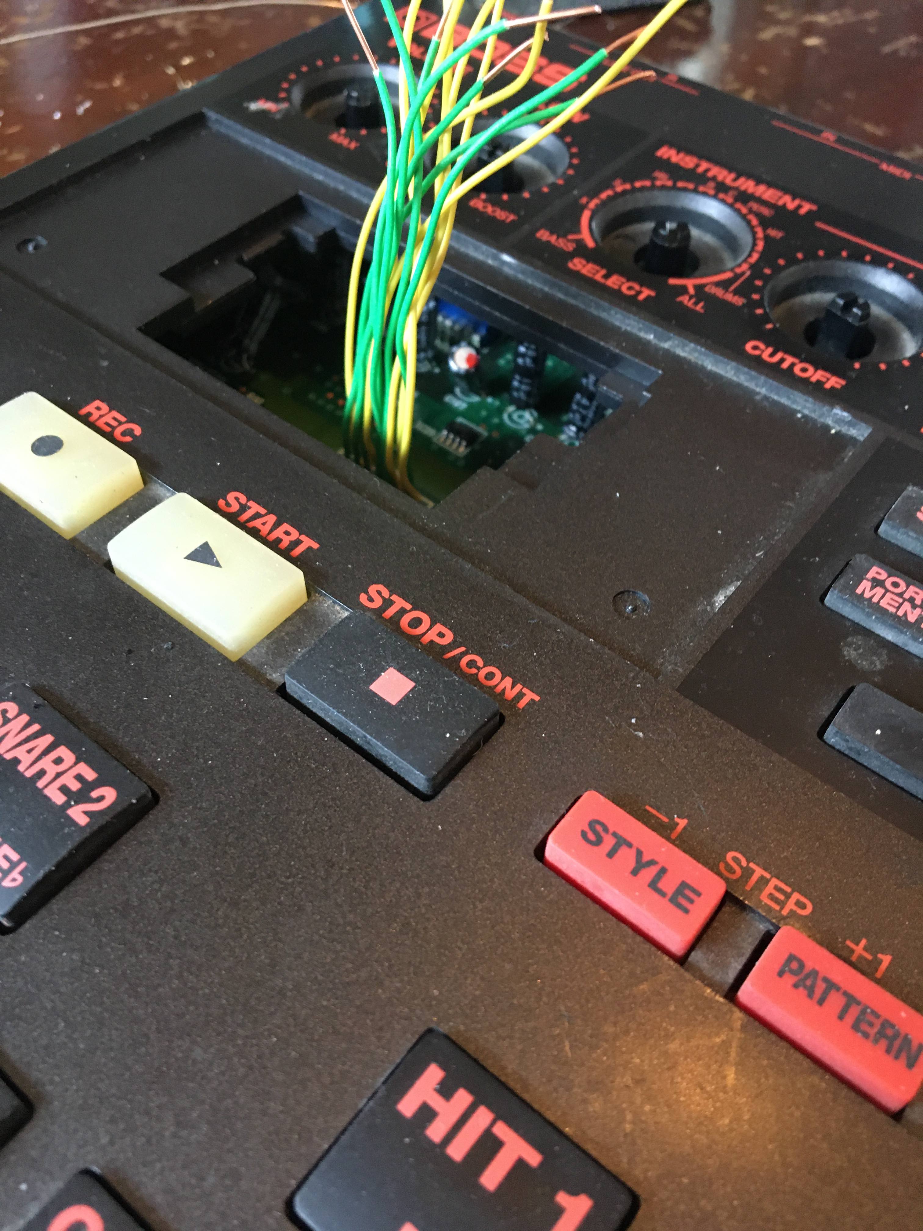
it’s not a 1 for 1 replacement because the FPC pinning must be done acording to my picture but it seems similar and the controller seems to be compatible.
You’re right…that pin sequence wouldn’t work…
good new! ![]()
Worked right away! Your suggested pin hookup was perfect. One question…when I hook up the backlight, it’s nice and bright, but the text becomes quite dim. Is the backlight drawing to much power? If so, could a resistor in series with the backlight power supply solve the problem?
Perhaps the contrast must be increased a bit in the DR-202 settings.
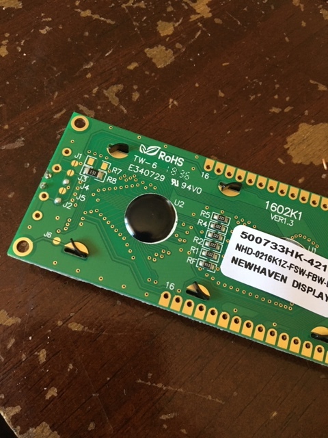
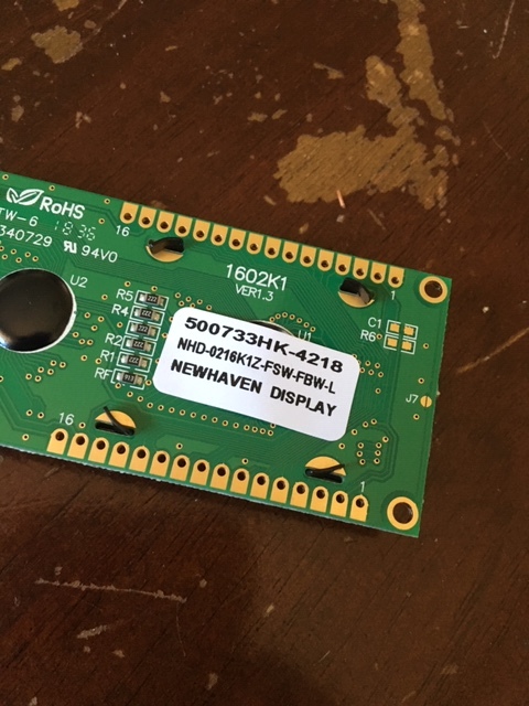
You confirm there’s a resistor for the backlight on the back of the LCD? I think the led would not have survived without it and the datasheet say it’s normally included. But to be sure, can you show your backlight wiring and a picture of the back?
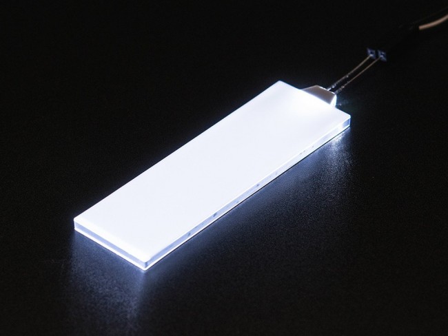
such LCD with white led is very bright compared to the old yellowish green LCD.
if you have some resistors you can add one in serie with one of the backlight wires to decrease the brightness.
it’s bright like this:
Ok ![]()
it’s perhaps because the new LCD requires a lower voltage (near ground) on the contrast pin than the original one. but we don’t have its datasheet.
so in this case you have 3 solutions ![]()
-
tweak some components on the mainboard but it requires high electronics skills (replace the buffer with rail to rail one and tweak PWM filter values to go lower)
-
add a serie resistor with the backlight to decrease the brightness and keep a good contrast (in the dark there’s no need of a very bright light background)
or -
disconnect the wire connected to the pin 3 of the LCD (Vo) and connect a potentiometer between the pin 1(0v) and 2(vdd) of the LCD and its wipper to the pin 3 (vo) of the LCD like in the datasheet)
but you will not be able to adjust the contrast in the menus anymore.
you can test this solution by directly connecting the pin 3 to the pin1 of the LCD to get the maximum contrast level after removing the wire from the mainboard to pin 3 of the LCD.
Excellent advice, Genesis. Thank you. I’ll start with #2. I like the backlight, but it doesn’t need to be soooo bright…so I think a resistor is where it’s at! 10K ohm? I have a bunch of resistors…lots of different values…
Here’s the datasheet for the LCD…
yes I was talking about the datasheet of the original LCD to compare with the new one ![]()
for your LCD the internal resistor is 130 ohms and that give 13mA (5-3)/130 = 15mA
the led brightness is linear with the current so if you want 50% less of brightness:
2/(130+x)=7.5mA → X = (2/0.0075)-130 = 136 ohms you must add a resistor with a value near 136 ohm (120 for example) in series with the pin 15 or 16 of the LCD to get 50% of the actual brightness.
if you have a potentiometer, you can connect it instead of the 120 ohms resistor, adjust the right brightness with it, disconnect the potentiometer, measure its value with a multimeter and replace it with a resistor of the same value.

You’re welcome ![]()
The contrast is set a little bit too high.
The good value is when you don’t see the rectangular grey blocks in background, only the characters.
But if it’s ok for you, you can leave it like this ![]()
Nice one!
How did you manage to fit the much bigger replacement LCD?
Assume you had to widen the opening and then mount the LCD somehow to the plastic case.
Can please you provide details (pics?).
Thanks!