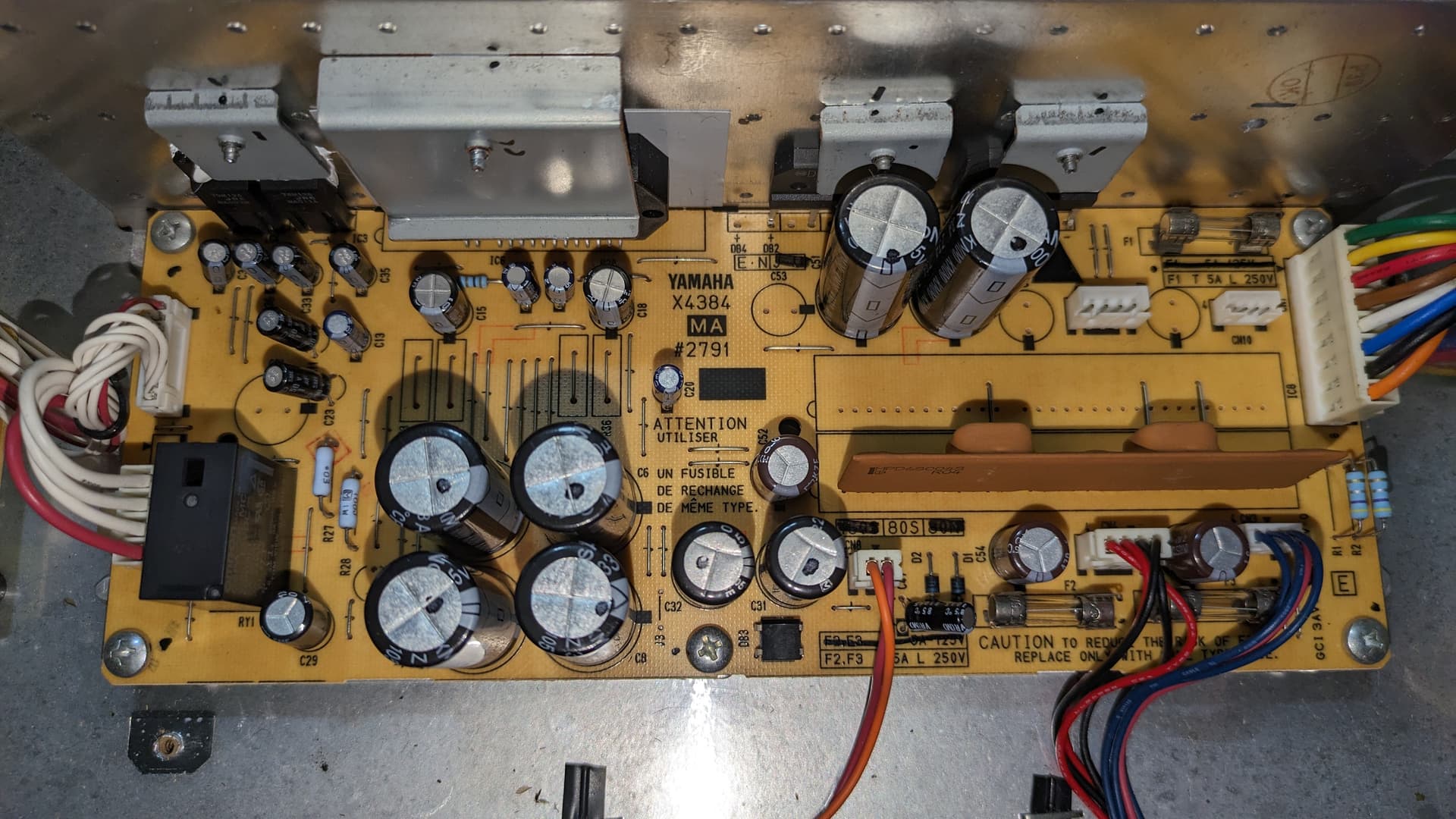
I am looking for some some specifications on the transformer X8264 and the power supply board X4384 for a CLP-340 Yamaha clavinova – especially before I start ordering parts I cannot return.
I have “output” from the transformer, but I don’t know if correct voltages. The power supply board has no output, I never hear the relay. No caps are bulged, no signs of burns. All fuses appear intact.
I was able to find the service manual but it is not that clear.
Has anyone had luck fixing these power supply boards and if so can you provide guidance? I have tech skills, DVMs, oscilloscope, soldering/resoldering etc.
So I should point out that although I have the red LED ON (left side of keyboard), neither the main 3digit display nor any other indicator lights are on.
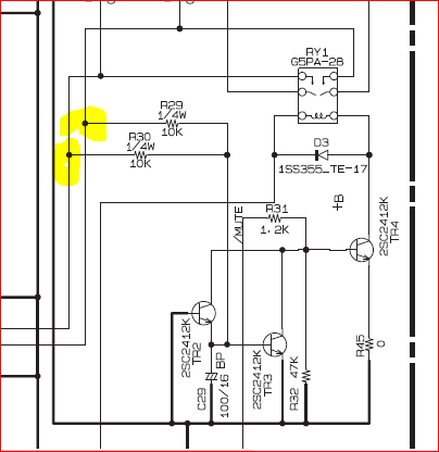
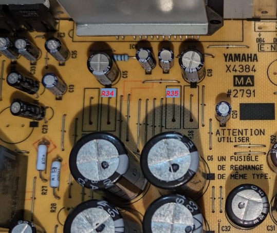
Double-checking the R34/R35 jumpers, same line as your yellow markings: 0V
No display - that is an entirely different story now!!!
The relay is kept off by a /MUTE signal from the CPU … if the CPU does not run that /MUTE signal is kept down - hence the relay won’t pull.
Now have to look at the main board instead!!!
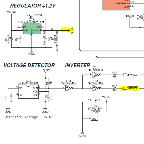
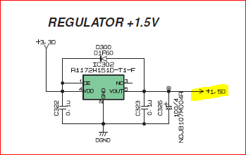
There are two IC’s on there that make 1.2VDC (IC2) and 1.5VDC (IC302) respectively from the 3.3VDC supplied from the PSU. Check both Vin and Vout on both.
At the same time also check the /RESET signal from out of IC3.
Yes I do, 100MHz Tek, 10MΩ probes. Let me know what lines are best. Not a storage scope though, so I cannot capture transients. It’s on my wish list – logic analyzer in general.
Here is what I found so far on schematic:
On CPU (SWX02): Pin 13 (16.93MHz out)
On SWP51L (tone generator): Pin 208
DM9000AEP (X7029A00) LAN Controller, Pin 19
I just read through real fast . Relay not engaging? Replace it ! Continue on from there.
I have got caught many times by a bad replay. You can also pull it out and test it with a bench supply. For the cost better to just put a new one in.
To any and all following this: I am taking a break to fix a few other easier projects. However, it dawns on me the 40W power amp might be the issue. The relay works fine (tested on bench) but the signal lines are low, inhibiting the relay’s activation transistor. /MUTE was high last I checked.
Fortunately these amps are still readily available but will need to desolder to verify on bench.
Short of this idea, the only thing left is either race condition with DM board or simply logic. Logic analyser is in order.
OK, back at it. The primary crystal X1 to the controller is happily oscillating at 16MHz. Are the DAC clocks, MCLK & WCLK0, really useful to look at? Read on.
The PNL & PNR are completely blank. Red LED above the headphone jack is lit (12V is working). All other voltages and sub-regulators were fine (see above). RESET is held high.
This is a gamble. Buying a new board is $350. What is the likelihood this board is just plain broken? I cannot get money back for the new DM PCBA. So I am hoping for any other suggestion that will confirm the DM is dead.
Assumptions:
the DM board drives the display. The PNL&PNR are all more or less passive components, LEDs, LCD etc. No power supply requirements to these boards.
all the rest are Keyboard, USB, LAN, MIDI, pedal ports (primarily input), not ones that cause the DM to not function, or lock it up.
/MUTE is asserted, i.e. mute ON (controlled by uP), RY1 is off, and still no display on PNL or PNR. I have tried messing with headphone inputs, but no effect.
To anyone following this thread: New DM board fixed problem beautifully. CLP-340 sings and plays. I have not gone through the full calibration. Thanks for all the suggestions.
Unrelated: One A2 is playing loud on easy presses, likely dirty – somewhat involved process of disassembly to clean contacts. Will live with it for now.
Found a reasonably priced supplier online for the DM board
Hi jakeo25
Really interested in your problem with the clp 340 I had similar problem with my 340 the power just suddenly went. My background is mechanical so limited experience with pcbs etc I decided to do basic checks starting from power supply, this is a 100v piano built in Indonesia hence has a external transfomer, this checked ok 115v output, so then checked pre power supply board, then the power supply board (x4384) checked for loose wires etc and found the c32 capacitor a bit loose so gently straightened up pulled a few connectors and replaced my last try, plugged in and it all started up, sorry about the long post but my point is can I get a new board,if so where, if not can I replace that loose capacitor, just hedging my bets if I goes wrong again. Any help would be good,Thanks
Hi Jake,
Thanks for the reply, piano still playing ok at present, forgot to mention I’m in England but shouldn’t be a problem if I ever need this part. I will keep this info for when it eventually goes wrong, and may find a need to contact you again if that’s ok. I really appreciate your help thank you.
Regards Peter