So next week I am lucky enough to do an autopsy on a DX1 power supply which had 240v plugged in to its 110v input. Anyone faced this situation before?
I was thinking of swapping it out for a pair of Meanwell type switch mode PSU’s although the 1.2v might need extra thought.
Also on Syntaurs website it has +/-12v regulators instead of the +/-15v shown in the schematics?
Does anyone know the power consumption for each power rail?
I’ve used this method before to replace the original supply with a newer one on other synths.
For the 1.2v rail, you can buy modules that DC-DC step down. The adjustable ones would be preferable for 1.2v.
As for power consumption, I really don’t know, but the +/- 15v usually isn’t a lot. The 5v rail draws the most current.
Yeah I have recently repaired an S1000 but was easy because the audio +/-V was made by linear regulators on the main PCB. I wonder if +/-V for audio switch mode would make the audio noisy?
I was thinking a pair of Mean Well RT-65C.
5A for the 5V (I could tack the 1.2v to that) It has 2.2A on the +15 but only .5A for the -15v
I was booked to take the PSU home to look over the blown PSU but I am starting to think I ought to bring the whole thing home to run it of bench power supplies.
I would think that’s a good starting point. You could always go up to the next biggest PSU if you were worried it won’t be able to power.
Most recent keyboards use a switching power supply so noise shouldn’t be a problem.
I wish you luck!
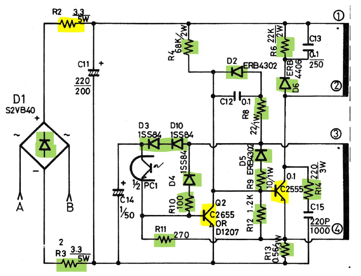
I repaired the power supply of a DX5 that had the same mishap.
I had to replace 2 transistors and a resistor on the primary (hot) part, less than $10!
The DX1 power supply is a little more complex, but it might not cost much more.
You have to test each component.
I took the opportunity to renew the electrolytic capacitors on the PSU, and add a small 220V/110V transformer to the input.
Awesome thanks for the hope. That was my plan, to bring the PSU back to the bench and test each component.
On the DX5 schematic, the faulty components are marked in yellow. The surge had caused the resistor to saturate, destroying the two transistors in the process. Everything else was unaffected.
On the DX1, the schematic is significantly different, but there’s a good chance the surge was limited to the primary, and perhaps also to the optocouplers PC1 and PC2.
Good luck !
Ok so I did a deep tear down, 2 of the diodes in the bridge rectifier had shorted. On top of that the main cap on the rectifier output to ground had shorted out. R2 (10r 7watt) had blown to a high value.
The Rifa caps across the mains switch are cracked so they gotta go!
I cant find any other issues, primary or secondary so I think there is a high chance it will be ok after replacing 3 components. I think I will put fresh caps on primary side just to be on the safe side.
There is a provision to switch the SMPS to 200V but in the UK we are 240V so I don not think I will try that out. And there a couple of resistor values different to the schematic.
So I have to buy a step down transformer to test it.
Hopefully it will start up without a load so I can test it.
Just switch it out of the 100V mode.
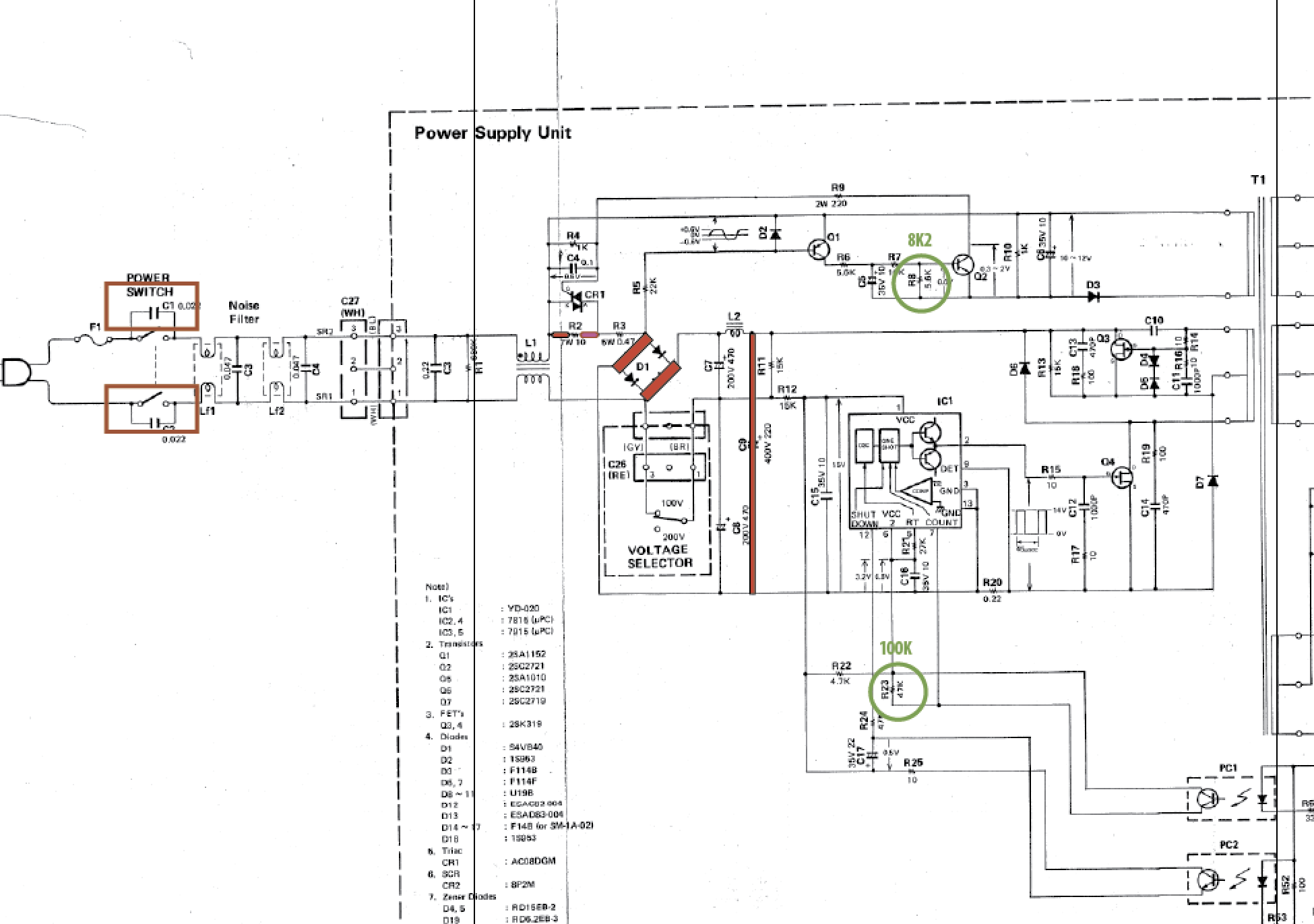
In essence - the rectifier on the primary converts the 230VAC to 320VDC and then gets “chopped” at a high frequency.
To get the same working at 110VAC that switch now converts the rectifier to a “voltage doubler” creating the required 320VDC to get the thing working correctly.
Now - when set to 110VAC and then connecting 230VAC to it, that “voltage doubler” will now produce 640VDC and that can or cannot be detrimental to some components.
Hence - check the Q3 and Q4 for no short S-to-D and also test the controller IC - feed the 15VDC onto its pins 1 and 13 and check with a scope that is actually runs and switches.
If these tests pass you are good to go at 230VAC (need to switch 110VAC OFF !!!)
I tried to run the switching circuit from 15V but nothing happened. I guess the Opto’s were not reporting back correctly.
But I plugged 110v (120V measured from my step down transformer) and it all works!
The 1.2V is measuring 1.7V. I think somewhere I saw 1.6V on a different schematic.
Does anyone have any experience with this rail?
Now I have to find the courage to put it into ‘200V’ mode. What’s 30V between friends?
1 Like
I took out the 100v link and it works at 230v now!!
Strangely I bought a cheap step down transformer from amazon and its IEC failed a PAT test at the polarity check!! It’s called LvYUAN. What a POS!!
2 Likes
Well done on this repair !
1 Like
Here’s part 1 of the repair.

1 Like
Here is part 2! Place bets now if you think the DX1 survived the over voltage input.

Did the DX1 survive?
Spoiler. Oh yes!
