[Ensoniq] [SQ-80] – [No Audio and Garbled display]
Hi all! I recently purchased my first synth (apart from a stylophone), an Ensoniq SQ-80. The Good: it was only $100 and came with a SKB case. The Bad: there’s a reason it was only $100 ![]()
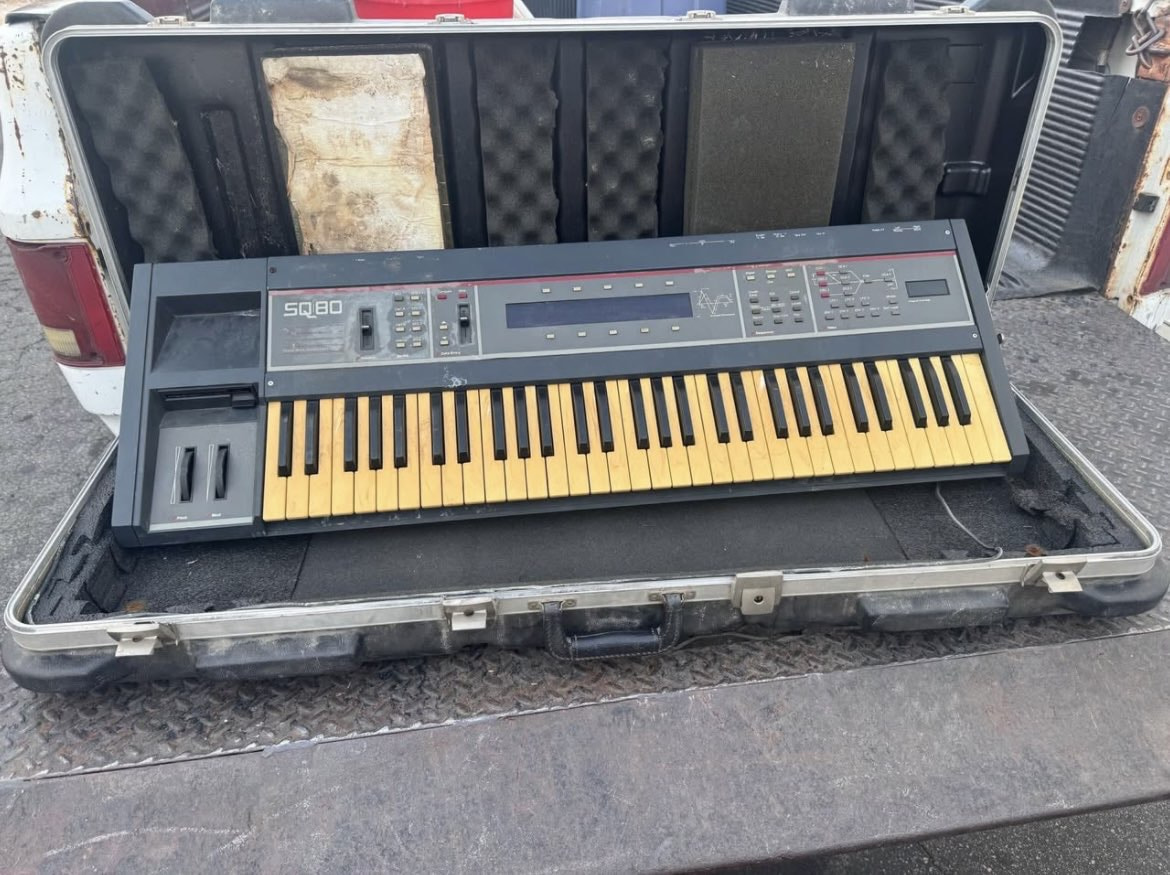
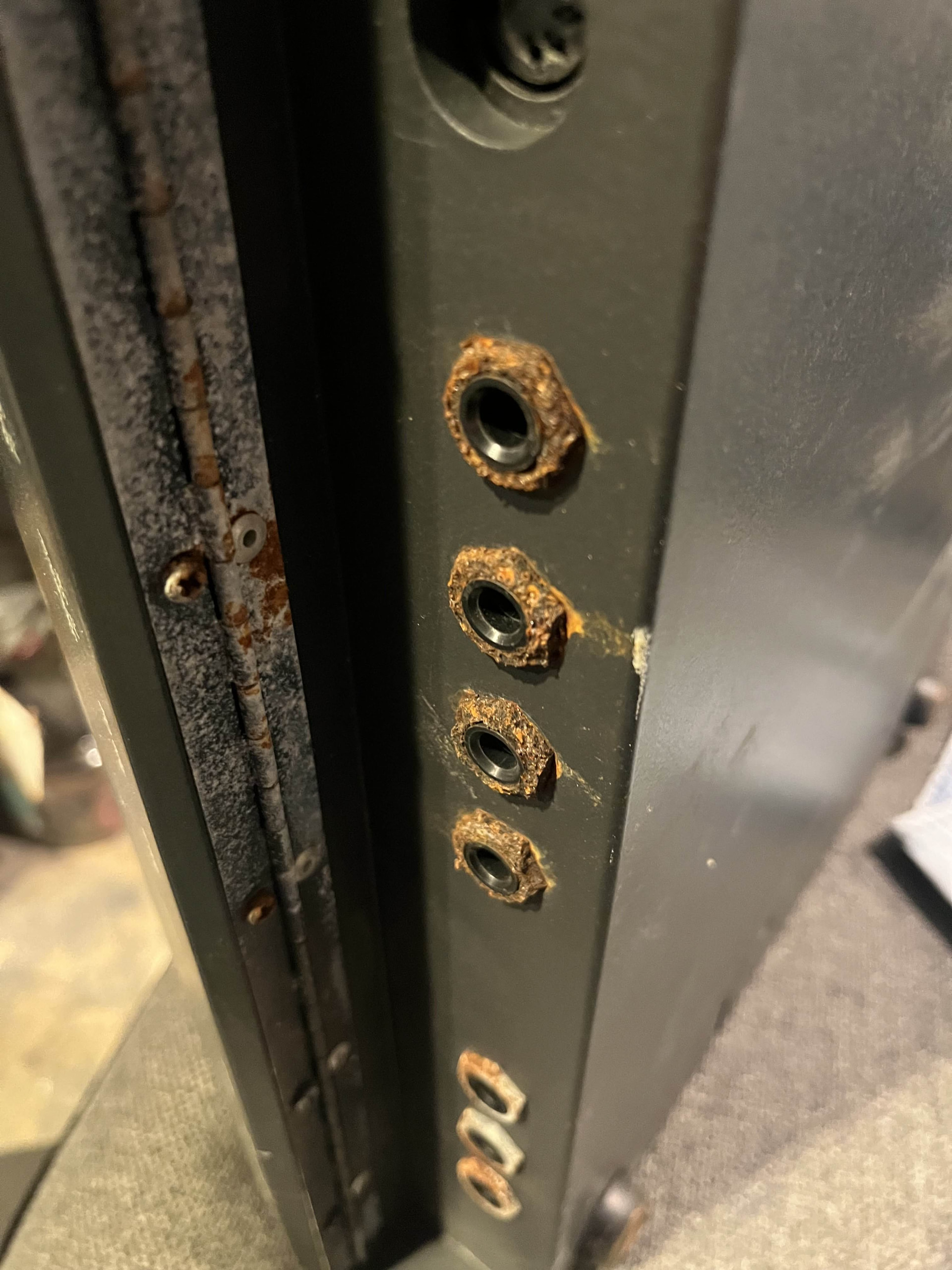
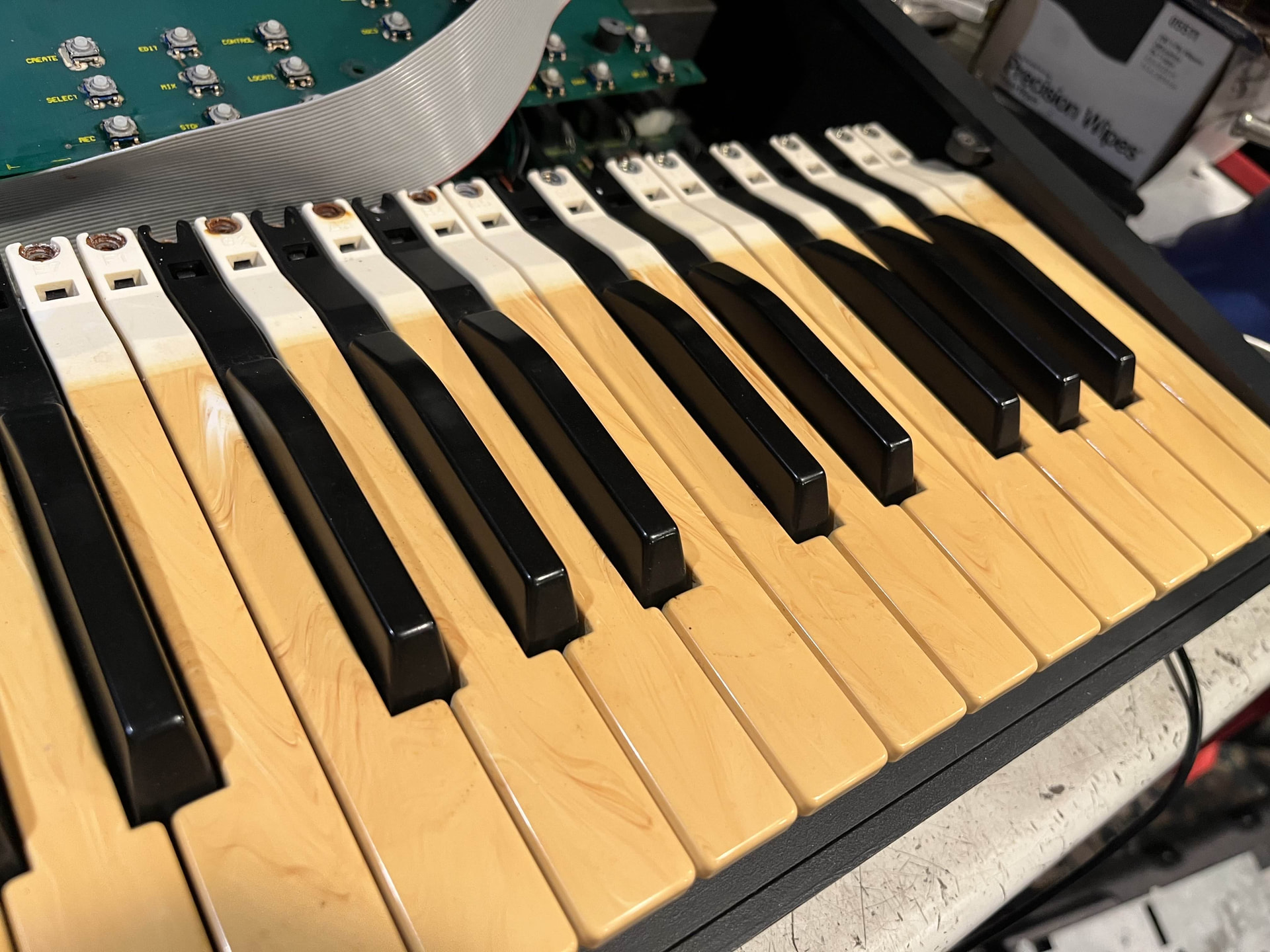
At some point this poor thing had a bath in some kind of liquid, as almost every single piece of metal has some sort of rust or corrosion on it. The keybed is super yellowed and almost looks like it has fake wood grain on it. Also it does not work (I know, what a shocker). No sound output and nothing on the display. Now although I’m new to synthesizers, I’ve been repairing retro game consoles for quite some time and am currently studying electrical engineering, so I’m not a complete newbie.
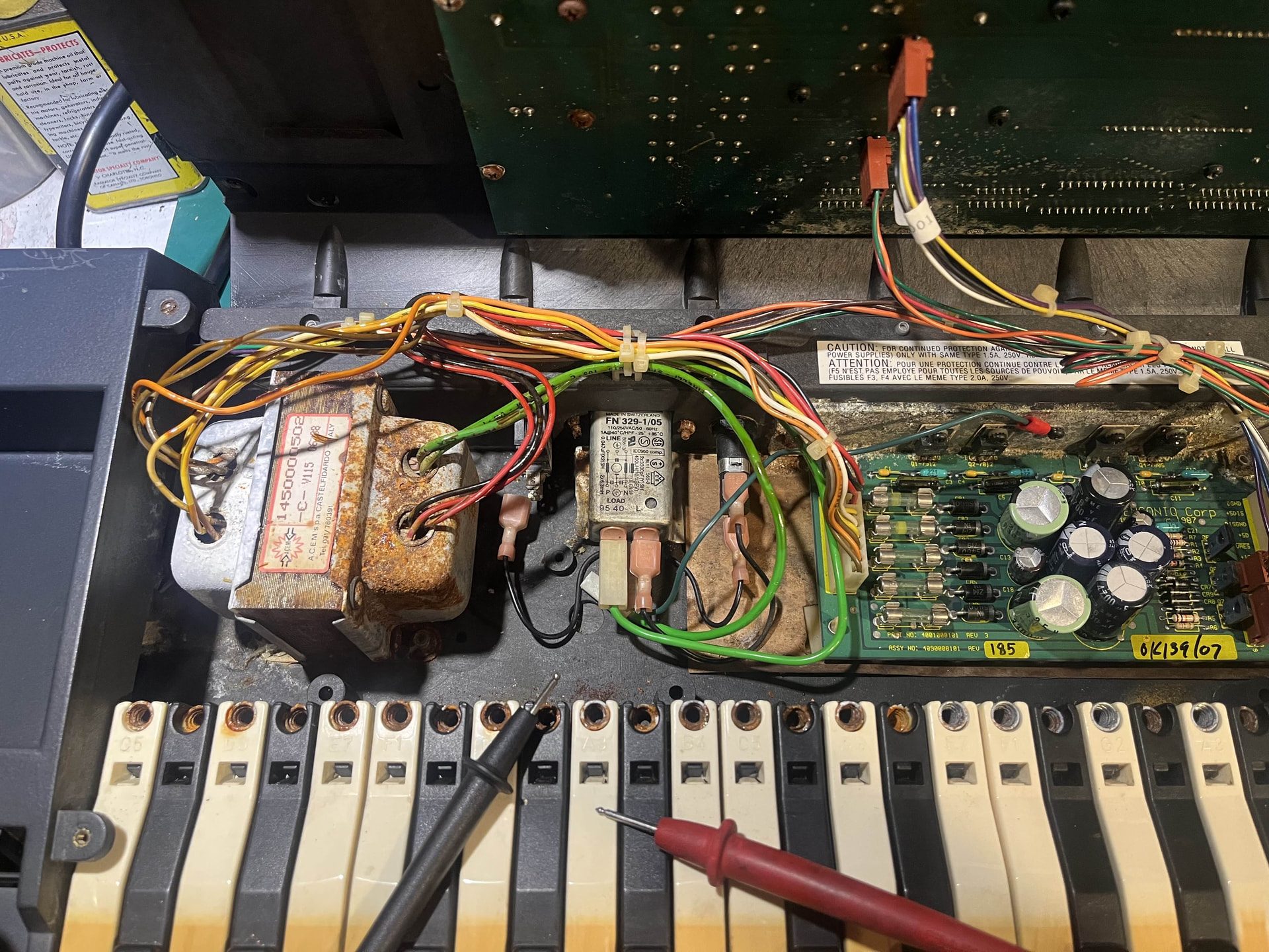
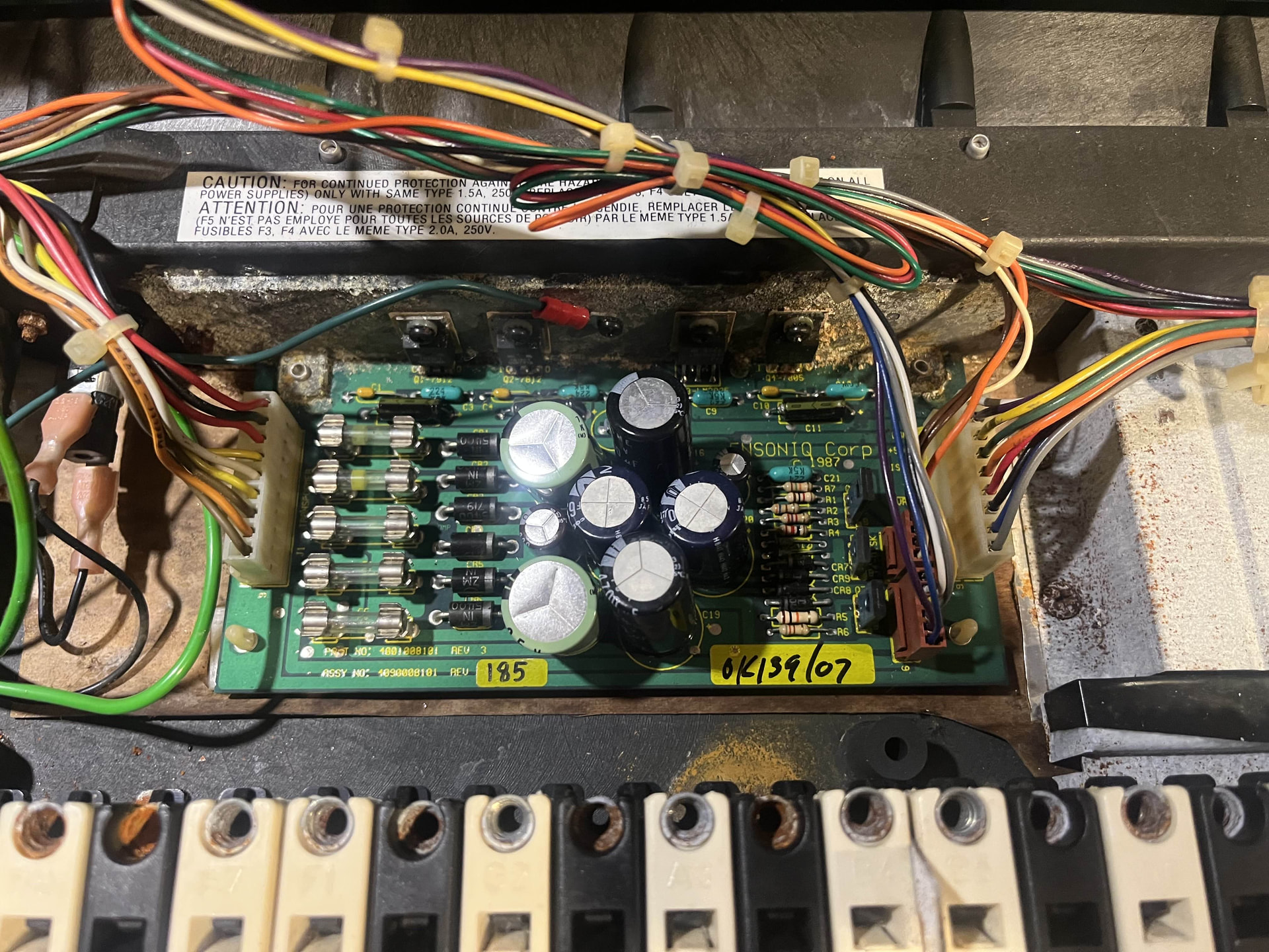
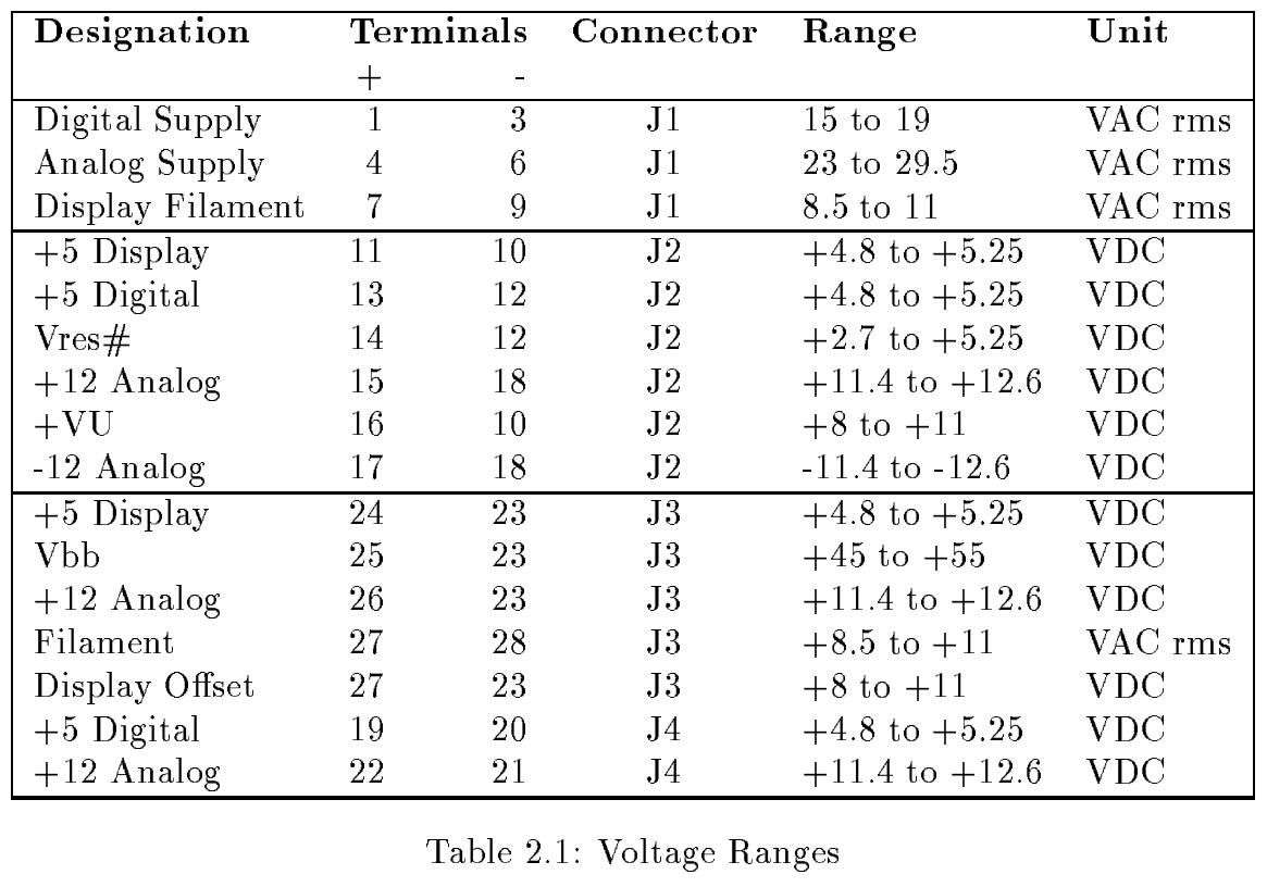
I started off with checking if I was getting power. No continuity on the power switch let me know it was broken. I ordered and swapped in a replacement (thanks for the switch Syntaur) and checked my fuses which were all good. Then using Buchty’s service manual, I was able to check the voltages of my power supply and they were all within spec (despite how gross my transformer looks).
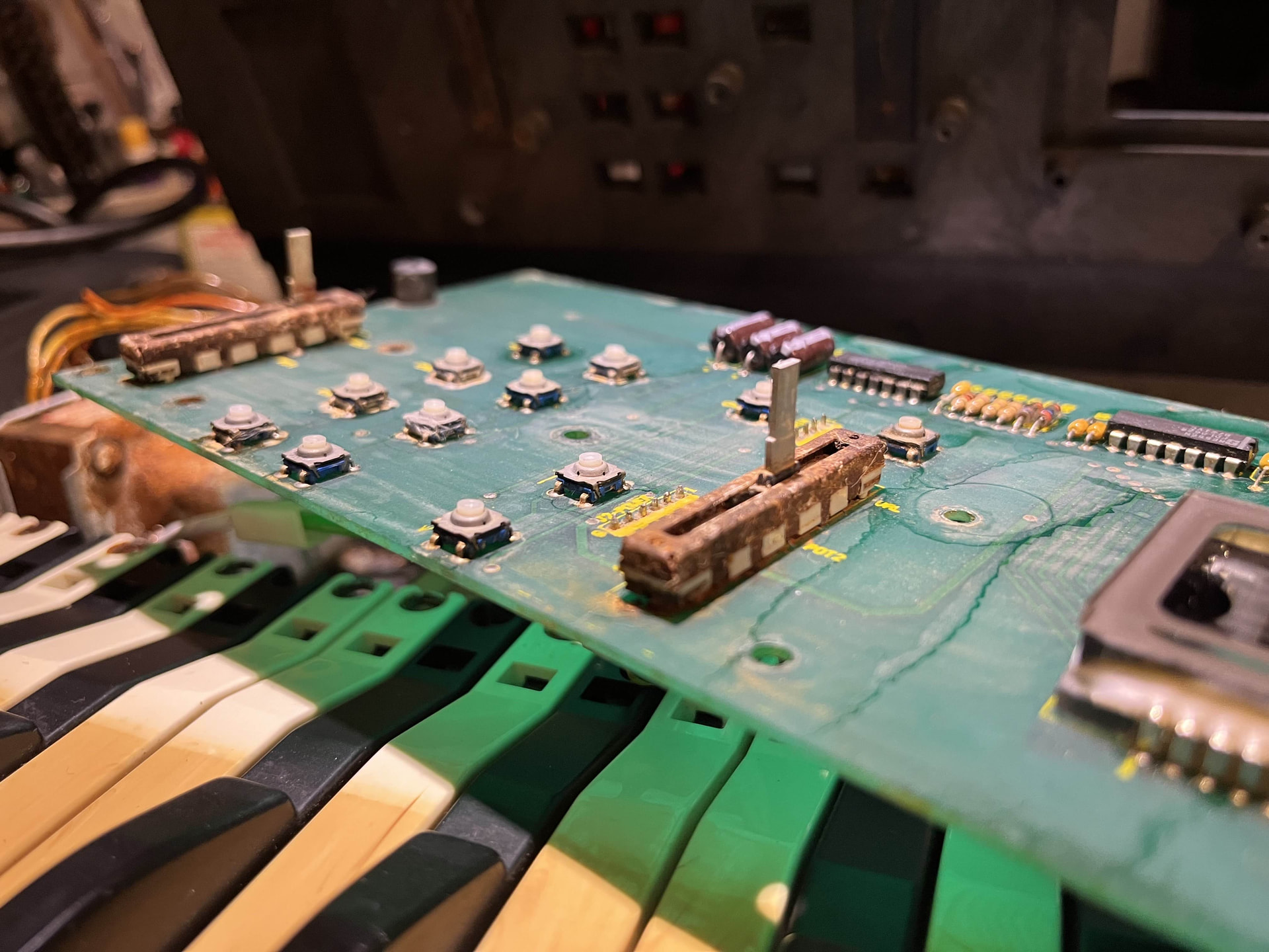
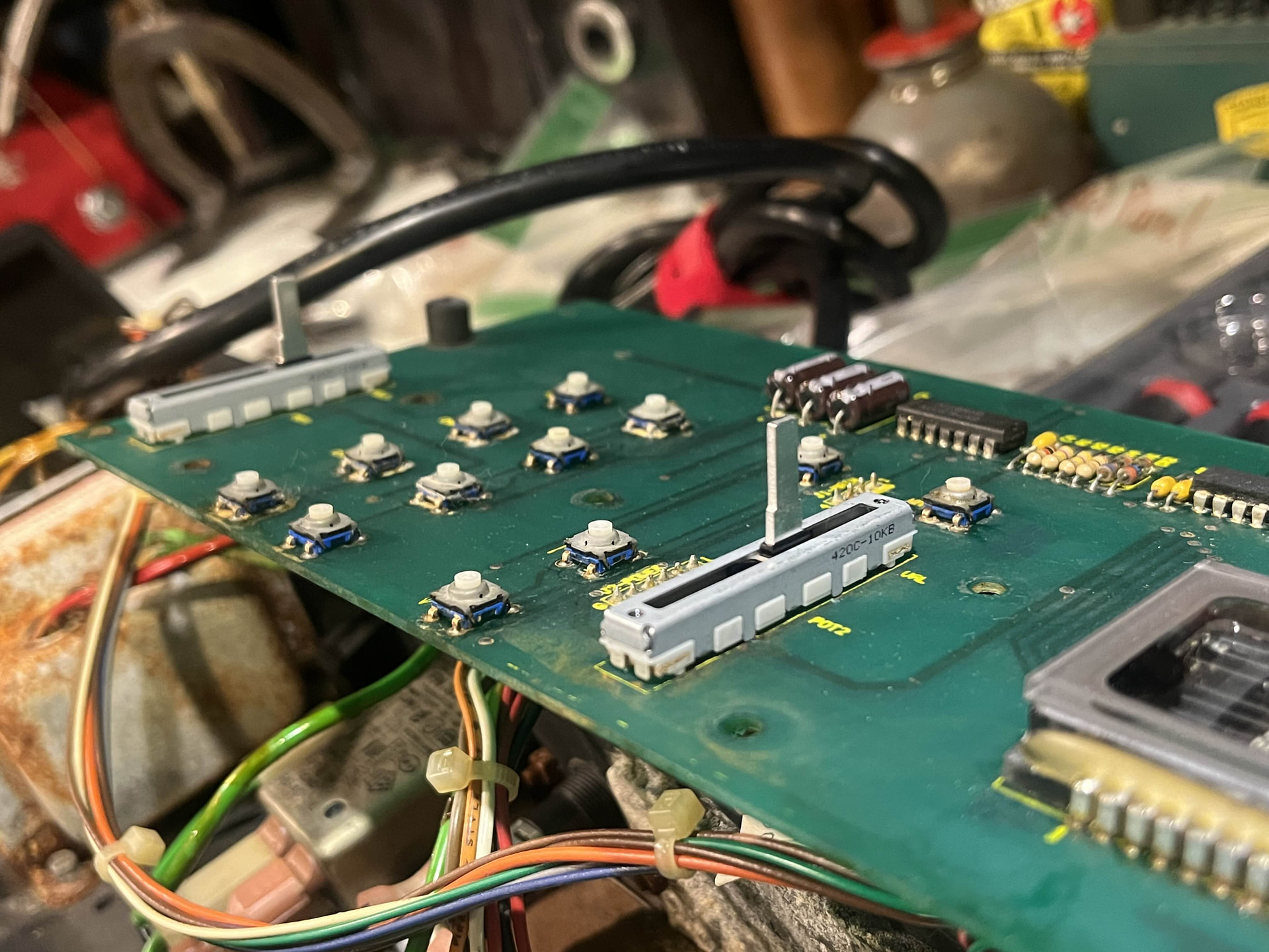
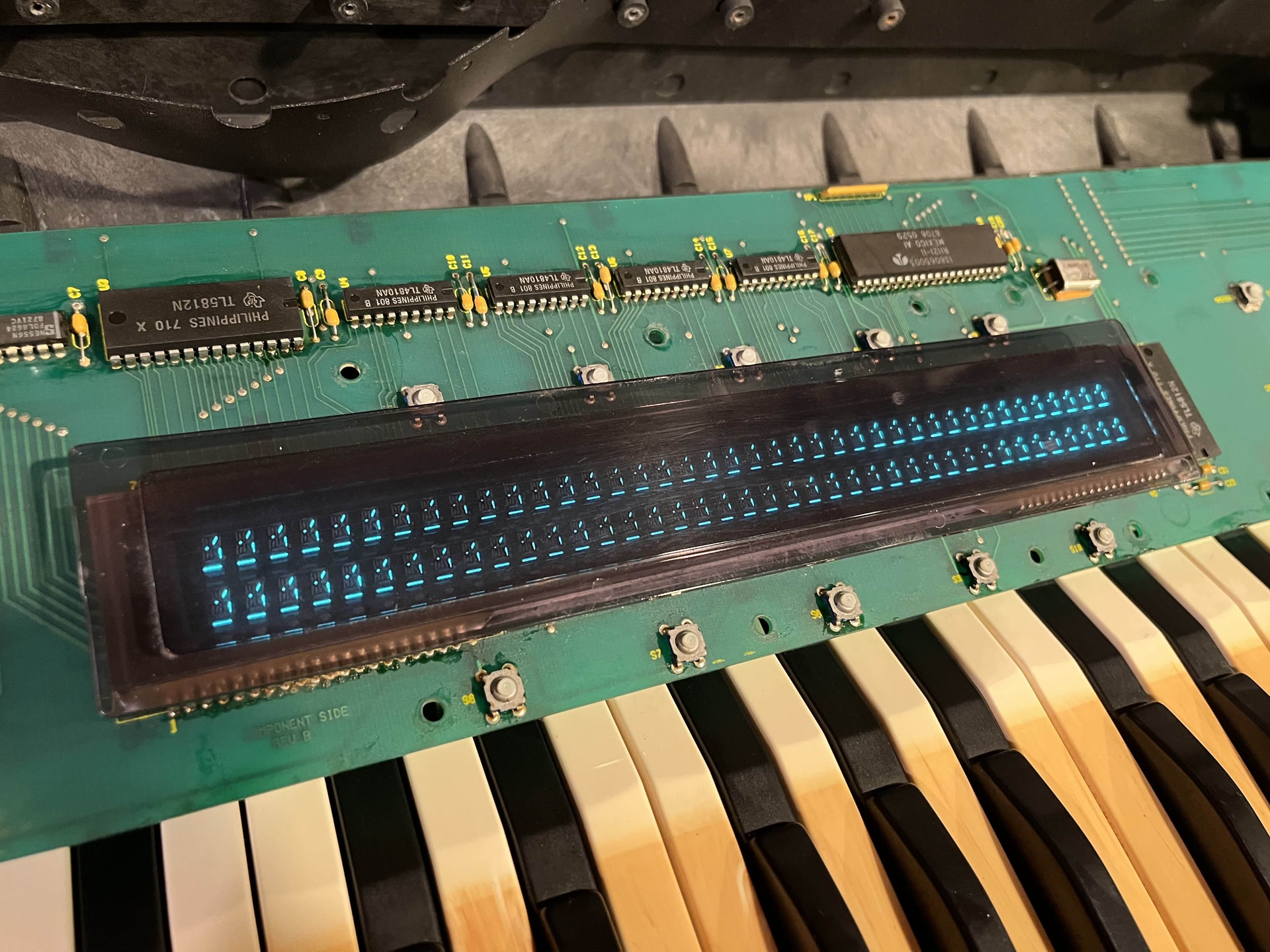
I then started diagnosing the display board. I unplugged the 4-pin connector so that it wouldn’t receive any data from the main board, which should have put it in the test mode where button presses should display random characters on screen. This did not work and no characters appeared. HOWEVER, I also had ordered a set of replacement faders for my volume and data entry sliders that were rusted in place (thanks again for the parts Syntaur), and when I soldered the new ones in and plugged everything back in, my display was on and displaying random segments across the entire display. I don’t know if this was because the heat from the soldering iron reflowed a cold joint or just from me unplugging and replugging connectors.
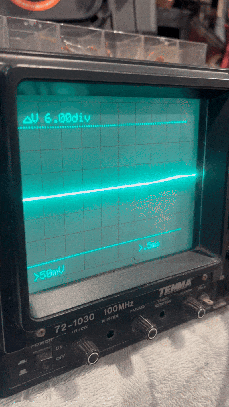
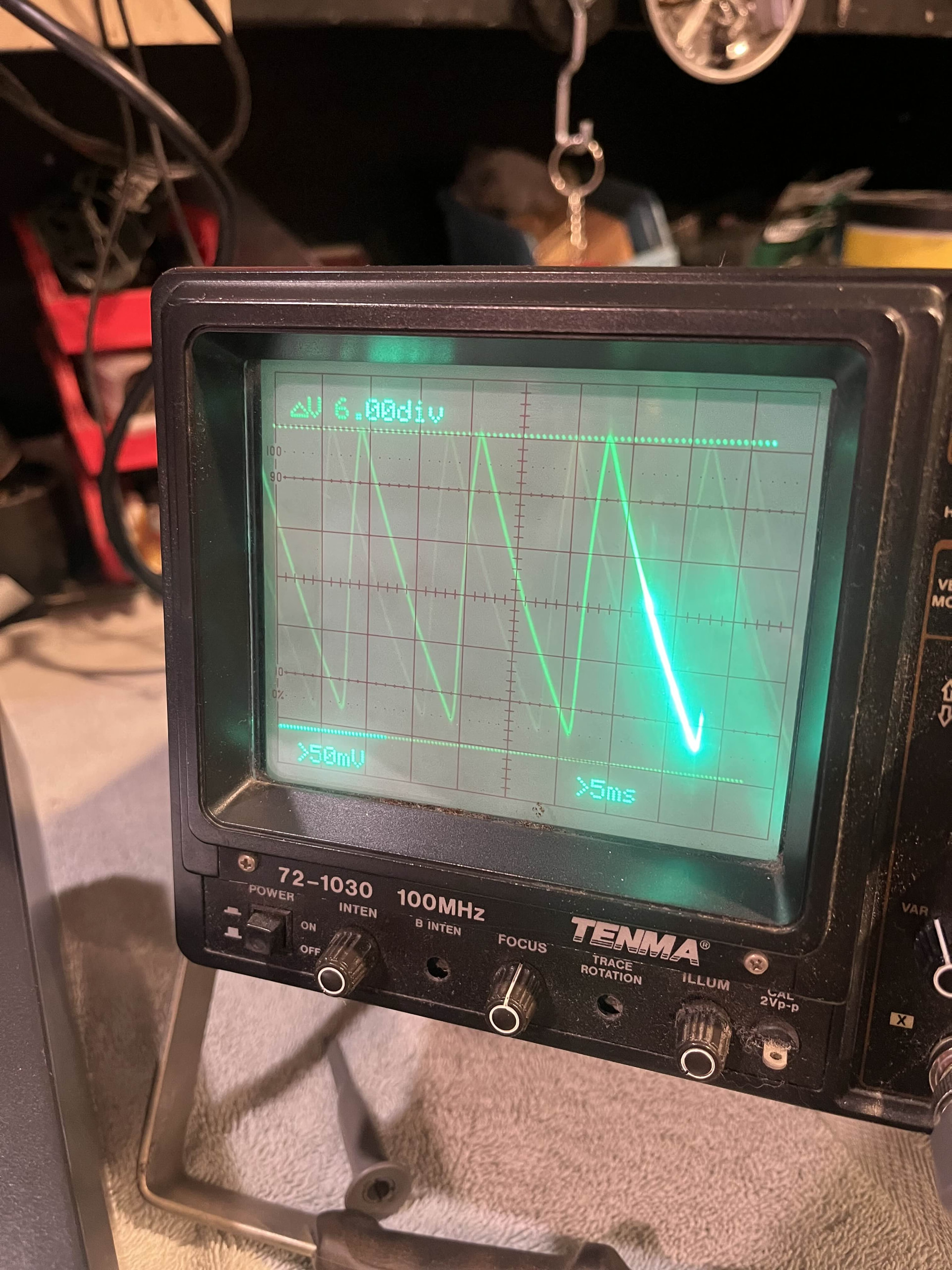
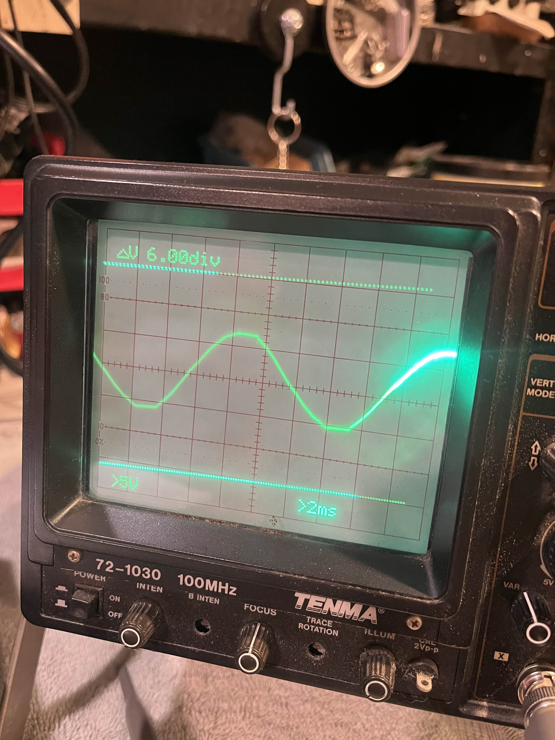
I still can’t get any sound to output. However when powering down the synth, it makes a noise that sounds like a frequency sweep going from low to high (Almost exactly how Antilles describes it in his post Ensoniq SQ-80 DOA ).
I have unplugged/replugged every ribbon cable/connector and the two OS EPROM’s to see if I just had a dirty connection somewhere, but that has not fixed anything either. I also tried resetting the RAM by shorting R1 to to the lower left pin of U50, to no effect.
I think my next step is to replace the OS EPROM’s incase mine are corrupt (plus it’d be nice to have the updated v1.8). I believe I will also need the KPC 1.5 EPROM, but I’m not sure.
I did get ahold of one of Rainer Buchty’s Display Panel Kit’s, but haven’t installed it yet. (https://www.youtube.com/watch?v=Pas89x2WEC4) The ESQ1 screen in this video does look similar to mine, however the one in the video still produces sound.
Also I recently rechecked the voltages on my power supply and on pins 16 & 10 (Designated as VU in the service manual) it is supposed to read between 8–11 Volts where was getting ~12.5V. I don’t think this is too big of a difference, but am not entirely sure
If anyone has any tips or helpful info for me I’m all ears. I really hope I can get this thing up and running.
.jpg)