Hello,
I recently replaced all capacitors on the power board of my JX-8P (all to spec in terms of capacitance). The new caps have a higher max temp rating than the original ones, and the two 4700UF 35V caps I replaced with 4700UF 50V ones (all are Nichicons).
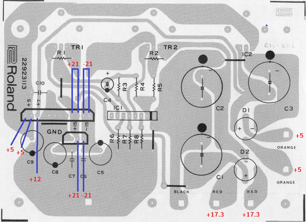
After replacing the caps I left the module and mainboard connectors disconnected and switched on the JX8P to measure and ensure the power from the power connectors was to spec. I measured the following voltages:
The numbers are definitely off (where I should see +7V , I see +12V , and where I should see +15/-15V , I see +21/-21V ).
Also, I noticed the transformer’s secondary voltages are also a bit off (5V instead of 9.6V and 17.3V instead of 19V). Inputs measure fine.
Just wondering if someone could shed some light on this one. I am not quite sure if the transformer is at fault here, or the regulator (M5230l)? Any advice would be greatly appreciated!
Update:
I desoldered the black, red and orange secondary wires from the power supply board and measured the Voltages again.
Every thing is the same, except for one of the orange wires, which now measures 0.9V
When I put it back in circuit it measures 5V again. Thinking the transformer is bad?
Hi Jay,
What is your multimeter ground reference test point. Was it all working before you replaced all caps…?..Any cap with wrong polarity…check for solder bridges…
Hi Mtnelectronics:
To be honest, the reason I replaced the caps on the power supply board was in the first place due to another issue I was having with the JX8P (see link). The unit was turning on and working besides the issue in the link.
Stupid me, I should have performed the tests I described above before replacing the caps.
I did take pictures of the board before replacing the caps as I know that you can’t always trust cap polarity markings on the board itself. I triple checked to ensure all caps were resoldered with correct polarity. Couldn’t find any solder bridges either.
Any advice on how I should properly measure the transformer secondary, is it better to measure when it’s desoldered from the power board?
Thanks!
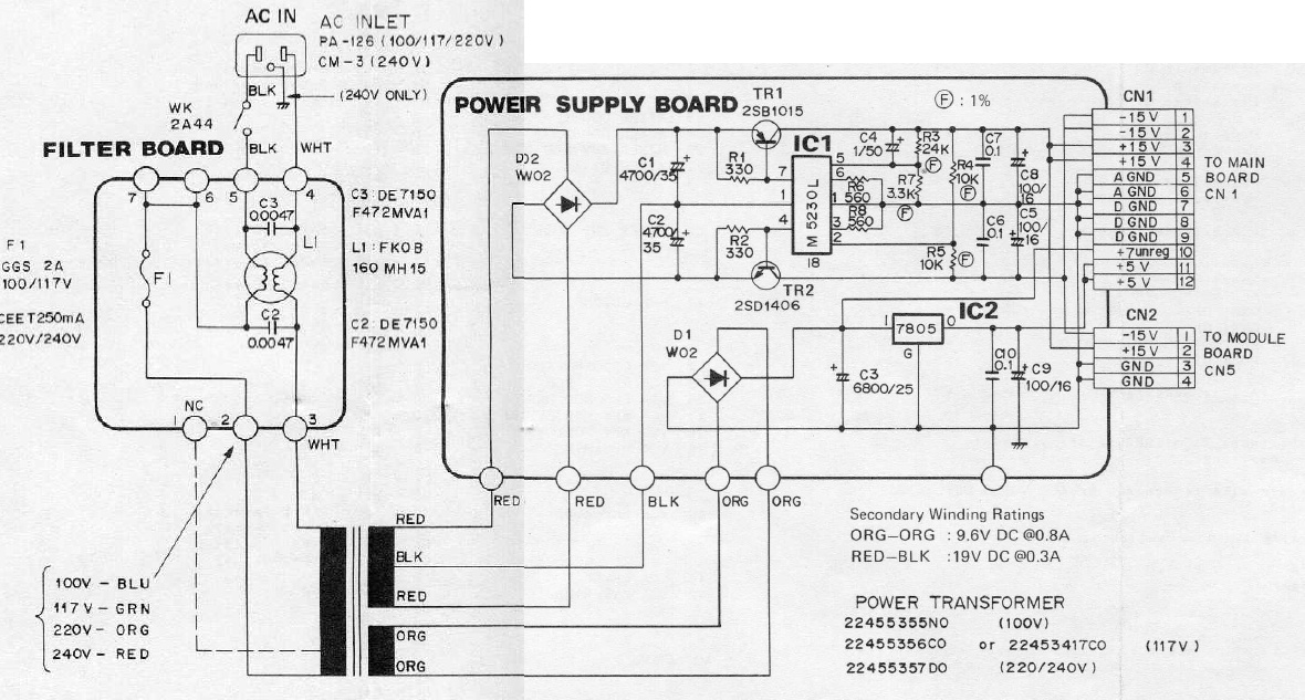
Hi Jay, looking at your first diagram, the voltages on the two red wires are AC, not DC as they come from the XFO, so there is no polarity there.; …same for the orange ones, these are AC voltages…Measure the AC voltages on XFO secondaries.
The black wire from transformer is centre tap and also the ground reference.TR1 & TR2 are “current booster” for the IC regulator M5230L…The output voltages for this IC are selected by the values of the resistors R 2,3,5,6. The base of transistors TR1 & TR2 should show +15 & -15,
See IC2 is more likely a LM7805T, a fixed 5volts regulator, all it needs is minimum 3-4 unregulated volts above it’s fixed output to give a well regulated out of 5 volts…
Will download the schematic and check…
If you measure voltages between pin 1 & 4 of the M5230L it should be about -15.6 volts and between pin 1 & 7…should be +15.6…The emitter of TR1 & TR2 should be much higher…19v to 25v…On the schematic diagram I downloaded, they show ORG-ORG : 9.6V DC @ 0.8amp and RED-BLK :19V DC @ 0.3a…this “DC word” is wrong, it’s an AC voltage…
If it’s really +21v & -21v that you measure, TR1 & TR2 could be short circuit as it would be the unregulated but filtered voltage from the capacitors C1 & C2.
Can you measure voltages on Emitter-Collector-Base of each TR1 & TR2…
If the transformer / power supply is disconnected from the mainboard, the power supply will read with higher voltages because there is no power draw on the power supply. The new capacitors are upping the voltage because they are expecting a load from the rest of the circuit board to be there to compensate for. Without that load they will just raise the voltage from the transformer.
1 Like
First thought: what series caps did you put in there? There’s a lot fewer choices at that size and voltage, but it’s still possible to stick in a cap with specs that don’t work well for a PSU a circuit.
Second: did you replace C3 with a 6800uF cap or a 4700uF?
This is a linear power supply, so there shouldn’t be much difference in voltage, loaded vs unloaded. The +/- 15V section is separate from the section producing +5V and +7V unreg, so if both aren’t putting out the correct voltage, I’d be looking at what’s common to them. I may have read too quickly, but it doesn’t sound the like XFO is the problem. What sort of voltage are you getting at the bridge rectifiers, D1 & D2? Are you sure your solder joints are good on those caps?
Hi Mtnelectronics,
Thanks for the reply. I noticed the error in the service manual as well (DC voltage indication for the secondaries instead of AC).
I measured TR1 & TR2 and getting roughly the same voltage on each leg:
TR1: 1.7/1.8V on each leg (minus the ground leg)
TR2: -1.6/-1.7 on each leg (minus the ground leg)
That doens’t seem right (might have to re-measure again later)?
M5230L (IC1):
Pin 4: -23V
Pin 7: 23V
Hi Madisynths & midnightvisions - Thanks for your responses.
C1 = 4700uF 50V (mfg: UVY1H47MRD)
C2 = 4700uF 50V " "
C3 = 6800uF 25V (mfg: UVY1E68MHD)
Rectifier output voltages:
D1 => +12V
D2 => +46.7V
I will triple check the solder joints on the cap later today, as well as from the other components.
update: I checked all solder joints and reflowed everything just to be safe, but I’m still getting much higher readings on the 12 pin connector (+21/-21V DC), and much lower voltage readings on the secondary side of the transformer.
Tonight I’m going to try to solder the old (big) capacitors back in just to see if this makes any difference.
I’ve installed the original capacitors and measurements are still off.
I also measured the capacitance on all capacitors while they were off the board (both old and new). One thing I did notice was that the newer caps measured a much lower capacitance value than the old ones.
For example, the new 4700uF ones measured only 4400/4500uF and the old ones 4700/4800. Not super dramatic but kind of interesting. Not sure if I will place the new ones back yet (any suggestions for a good alternative to the Nichicon MRD series caps are greatly appreciated!)
I hate to randomly replace parts, but I’ve ordered a new M5230L, as well as a new transformer. Well, the transformer I really ordered for my JX3P but I am probably going to install it in the 8P first to see if this makes any difference to the voltage discrepancies. Will post again once I’ve received the goods.
I would tend to agree with the no load situation. You should check if the service manual states load or no load. Most of my equipment service manual will indicate no load voltages or load/no load voltages. Having both can often help trouble shoot faulty boards beside the power supply.
Also these caps are for filtering ac ripples, so it doesn’t really matter if the actual rating is spot on or not. What makes a big difference is both the Temperature rating and the physical size of the cap. These are electrolic caps, based on water as the main electrolic. These over time will dry out, and cause the tops to bulge. You can wiki electrolytic capacitors. They have a great explanation and guides on what to use. Heat is the biggest limiting factor on all electrolytics. In my Ensoniq EPS, I had to install a fan so as to prevent the power supply from killing the caps. Behinger equipment is notorious at under sizing their caps, resulting in premature failures that almost will take the regulators and or chip controllers down. I would have checked the loaded voltages first before buying those extra parts.
Hi stealthy -
The original plan was to replace the capacitors on the power supply board as these were still the original ones. Besides the caps, the only extra part I bought was the M5230L IC. As I mentioned in my previous post, the transformer I bought isn’t for my JX8P, but I could use it to test with if I wanted to.
I looked at the JX8P service manual but cannot seem to find whether or not voltages mentioned are load/no load voltages. It’s kind of a crappy PDF with pages cut in half (I only found 1 service manual that seems to be circulating on the web).
Also in my previous posts up here I did test the transformer in an open circuit.
If they don’t specify, I would assume that these voltages are with load.
How are you measuring the AC voltages? It looks like you might be seeing the RMS value and not peak to peak.
Hi ProfTrudo,
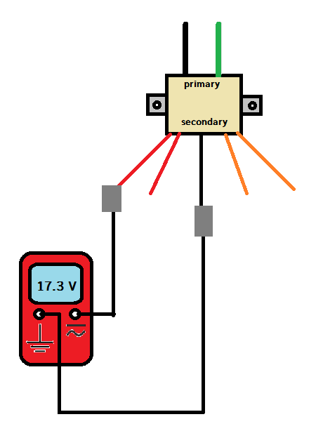
I measured the AC voltages on the transformer’s secondary when it was connected to the power supply board as well as when it was desoldered from it.
For lack of better explanation, I drew out how I measured the voltages:
(Sorry, I thought this would be the best way to explain how I got to those numbers)
I used 2 different multimeters as well, just to be sure.
So in both situations I got lower voltages than rated in the manual (so I guess these values could be nominal?).
When measured the DC voltages (CN1 and CN2), I actually got higher voltages on almost all pins (with the exception of the 5V pins).
I went to go check the voltages on the transformer’s secondary on my JX3P and I measured similar voltages:
Each RED: 17.2V
Each ORANGE: 5.1V
So it does appear the winding ratings in the manual for the transformer are peak, not RMS. I think it’s safe to say the transformer of the JX8P is fine as well, I suppose.
I also measured all DC voltages on the main/panel/jack/din connector pins. All measured within spec, with the exception of the +7V pin on the din connector, which measured 10V.
Going back to my original concern with the JX8P, what could be the reason that the 15V/-15V pins on CN1 and CN2 measure 21V, and the +7V pin on CN1 measures +12V? It seems a bit high to me.
You should be checking the AC voltage between the two red wires and the AC voltage between the two orange wires. This is likely why your numbers from the transformer are off.
Electrolytic caps are usually a 20% tolerance, so a 4700uF could be as low as about 3800uF to 5600uF. The values you measure are within that range. The Nichicon caps you chose should be sufficient for this power supply.
Just for shits and giggles, what is your incoming AC voltage? The average should be 117V, if your AC voltage is higher than that, then it could explain why the unregulated +7V DC is high.
Since I’m assuming you’re not exactly experienced in this area, this might be useful: the transformer is not a regulator, so it simply produces a ratio of the incoming voltage to the outgoing voltage. The orange wire winding produces about a 12:1 ratio to take around 120V AC down to roughly 10V AC. If you’re home AC is producing something a lot higher than 117, say 130V AC, then that might explain why the unregulated +7V DC is over 10V DC.
This is the section I would focus on, since it’s the simplest section, taking the incoming AC, rectifying it at the bridge (D1), and having it smoothed a bit at C3 to create an unregulated +7V DC. There’s still a bit of ripple on this voltage, but this is likely for the display, so it’s not as critical. That same voltage hits the 7805 regulator, and is providing the correct +5V DC, so that’s looking good. The 7805 could still be producing this +5V DC if it’s getting 10-12V at its input.
Hi Madisynths,
Thanks a lot for the reply and confirming the caps I used should be alright!
I checked the AC voltage between the 2 red wires, which is 35V. Between the 2 orange wires is 9.6V.
I did notice that the service manual actual states that the voltage between ORG-ORG should be 9.6, my mistake for measuring ORG-BLK in the first place. However it also states the voltage between RED-BLK should be 19 but I’m getting 17.3V.
My incoming AC measured today is 119/120V (sometimes I measure 2V lower but that really depends on the time of the day, year).
Your explanation about the AC incoming voltage makes total sense, but it looks like the voltage is not extremely high, or much higher than 117V.
Could the M5230L at fault here?