I bought a broken Korg Poly 61 some months ago. Of course the issue was that the original battery went and had leaked a bit. After cleaning up + performing the CR battery mod, I got the unit working without any issues. It sounded great and worked well for about 4 months.
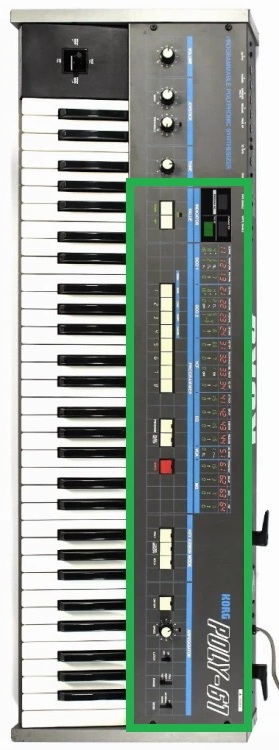
Yesterday I switched it on and half of the unit has no power. See picture below for better explanation:
So the panel/display board, center (KLM-481A) & panel board, right (KLM-482A) are not functioning.
Also, I don’t see the diodes light up on the voiceboard whenever I press any key.
The most left panel board KLM-477B seems to function, meaning, its getting power (frequency led is flashing).
I pulled up the service manual (huge thanks to Florian) and started measuring the voltage rails.
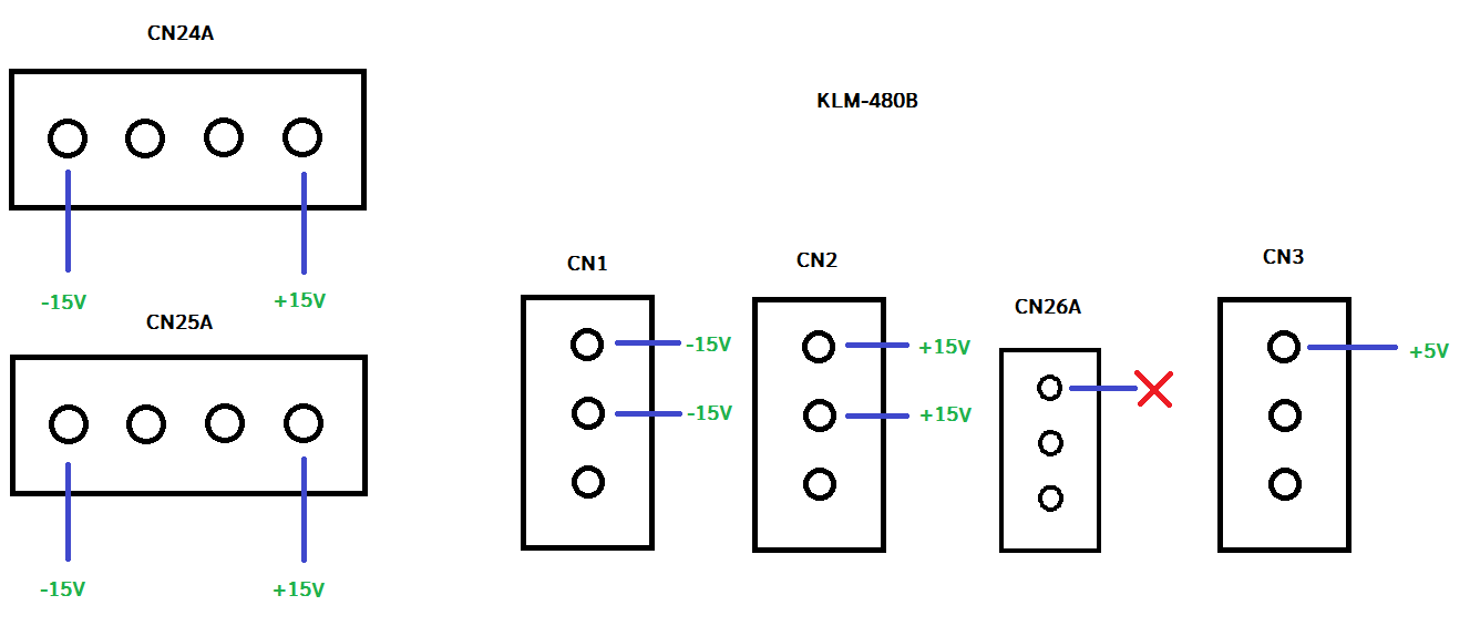
CN26A is giving strange readings (it’s hard to read in the manual, but what voltage is CN26A supposed to supply and is it the only power source for both KLM-481A and KLM-482A?).
I’m getting no steady voltage number, its fluctuating between 0-0.4V.
I was wondering if someone might have had similar issues with their Poly 61 and would be able to give some pointers? My Poly 61 is the early model btw.
The voltage on the CN26 connector should be 5V dc. Both the 481A and 482A are fed with this voltage.
The boards are also fed with +15V dc and -15V dc for op-amps and the frequency LED.
I would suspect you either have a short circuit on one of the boards or a failed component in the power supply.
Thank you Pat! It was kind of hard to read on the copy of the service manual I have, but thanks for clarifying the 5V output for CN26. I’m definitely not getting that value. I’ll have to do some re-measuring Voltages on the power supply board and make a list to out-rule there could be something else not functioning.
If anyone else out there has a better copy of the power supply schematic of the Poly 61 (page 9. of the service manual I d/l) I would be super interested!
I refreshed most of the power supply board this morning since I had a lot of the components in stock. I don’t like replacing components without knowing what’s going on, but it had to be done anyway since all components look to be original.
I replaced the large and small caps, and the 7805 but that didn’t do anything.
There is no full schematic for the power supply. At least not that i have found. There is however a pcb layout on page 14. Power supply for the 5v is pretty basic. A full wave bridge rectifier feeding a filter capacitor and then a 7805 regulator.
Try this:
Disconnect CN24A and CN25A on the power supply board. Those connectors provide 5V to the voice board and cpu board.
Disconnect CN26B at the display board.
Test to see if you now get 5V on the power supply board.
If you get 5V then you have a short on one of the boards.
Thanks again Pat for your suggestions. Even page 14 in my downloaded manual is very hard to read as a lot of traces are not clearly visible unfortunately
With CN24A, 25A and 26B disconnected, these are the readings I’m getting:
So I’m only getting +5V on CN3 as well as the 7805 input pin, nothing on the output pins which is odd since I replaced the 7805.
Another odd thing I noticed is that when I put the ground probe of my multimeter on the output pin of the 7805 and the red probe on PIN 1 of CN3, I’m also getting +5V (almost as if 7805 output is acting like a ground pin?).
*update: I left the power supply on for about 15 mins and the Voltage on PIN3 went up to +6.9-7V. That shouldn’t be an issue for the 7805 I’d imagine?
Maybe I’ll put the (what I thought was faulty) 7805 back and see what happens then.
Lol this thing drives me nuts. I just replaced the 7805 with another new one (L7805CV) and now I’m getting 0.1V on PIN3 of CN3 and the input leg of the 7805.
It looks like the power supply board has 2 rectifiers 1B4B41 and 4B4B41. It looks like 4B (marked as D3 in the service manual) that might be at fault here.
Looking at PB61-BP to replace which I think should be ok?
I’m getting the same Voltage readings from this rectifier compared to PIN3 of CN3.
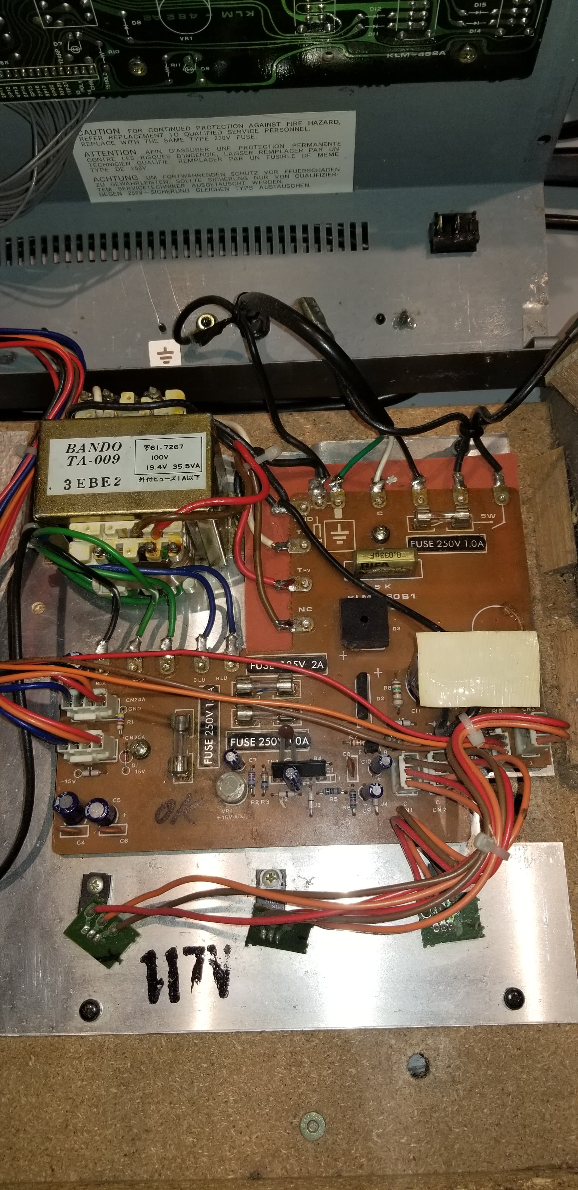
You mentioned that you had the early model so i have attached a picture of my power supply.
Hopefully you have the same power supply.
Time to start at the transformer and work forward.
Disconnect CN3 from the power supply board to remove the regulator from the circuit.
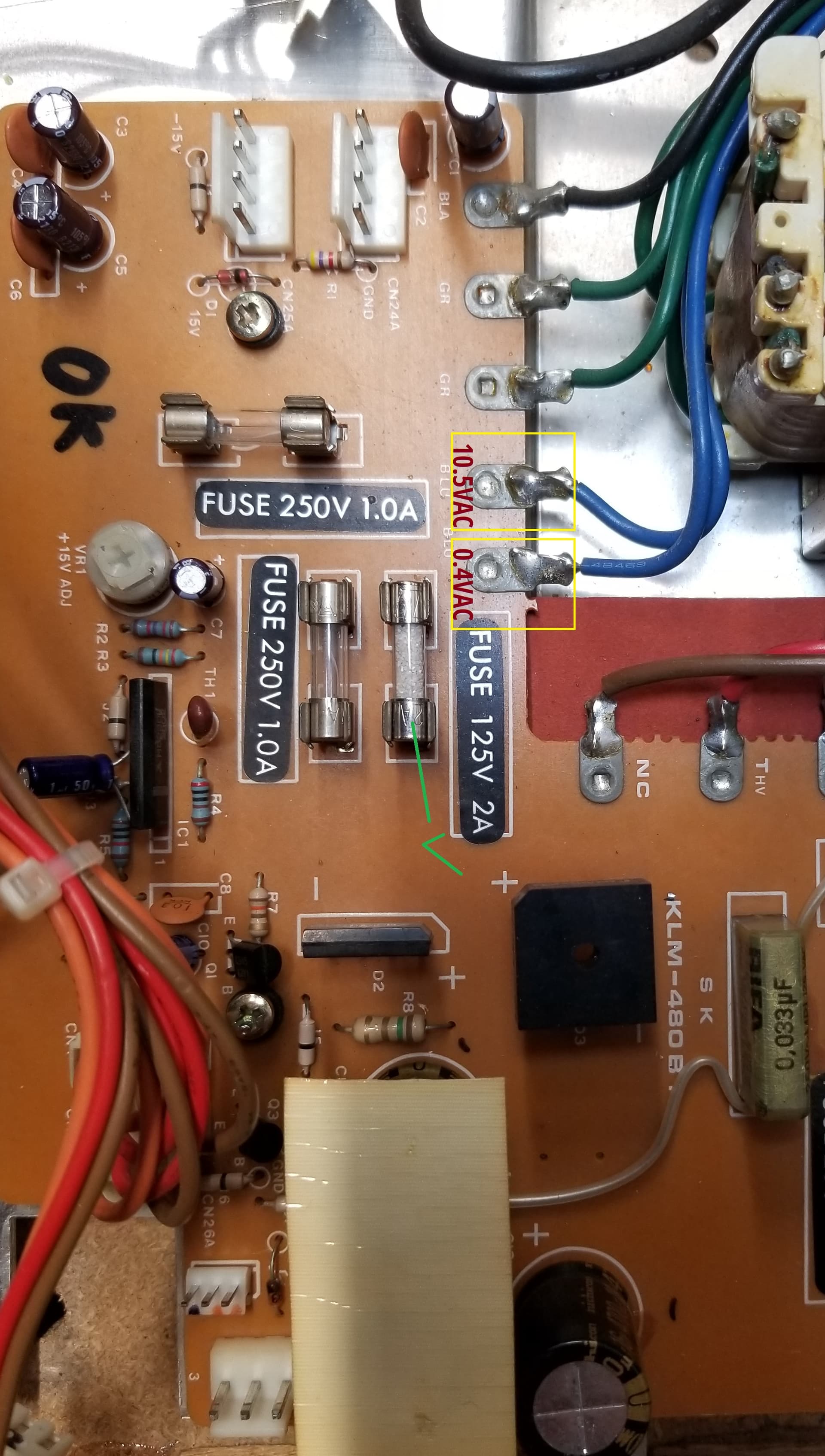
What voltage are you getting at the blue wires from the transformer to the power supply board?
Typical voltage should be 10-11 Vac.
Test the 125 V 2 amp fuse to ensure it has not blown from previous work.
Test the output of the full wave bridge rectifier D3. Typical value should be in the 12 Vdc range.
If everything checks good so far then check the wiring at the regulator.
(10.5VAC on the left blue wire, 0.4VAC - and it’s jumping values varying from 0.1 to 0.4 - on the right blue wire). The fuse tested good.
I was getting a similar values from D3 yesterday, except in DC (0.1-0.4VDC) but I’ll test it again after work but that makes sense if the transformer’s secondary is at fault?
Sorry if i confused you. The voltage reading on the transformer should be across the blue wires.
I have found that there a 2 different copies of the service manual available. One is described as a hi-res version which has a pcb layout of the power supply but without the schematic.
The other version that you have does not have the power supply pcb layout.
No worries at all I did it in a hurry during my lunch and didn’t measure it correctly. I was able to find the high resolution service manual as well. Definitely a lot better to look at in terms of PCB traces.
The voltage across the blue wires measures 10.78VAC. The Voltage values from the rectifier (D3) though are fluctuating between 0.1 and 0.4 VDC (sometimes steady at around .5V) however.
I’ll be checking solder joints or broken traces in a bit as well.
I ended up not finding any cracked solder joints but just to be sure I re-flowed the solder for the 4 legs of the rectifier on D3 which didn’t help unfortunately.
Next step would be to remove the rectifier bridge and check for shorts between the + and - of the pcb trace of the rectifier. For reference the bridge rectifier is rated at 3 amp and 100 PIV.
If no short is found install a new bridge rectifier and check the + and - voltage.
Thanks yeah I already tried doing that last night but the rectifier is a bit of a pain to remove and I didn’t want to destroy the board. I think I might have to cut the legs of the rectifier so I can remove each leg from the board more easily.
I do have some new rectifiers coming so I’ll let you know how it goes - cheers
During my lunch I was able to remove the rectifier.
The bad news, I had to cut the legs of the old rectifier to remove it properly. I broke one of the pads (it lifted and came off). I had to scrape and create a new solder joint
The good news, I switched on the Poly and measured the +/- legs of the newly installed rectifier (PB61-BP) and the output Voltage is 13VDC.
I want to replace the 7805 again with a different one again as well, just in case, and will test all Voltages (leaving CN24,25A disconnected).
I replaced the 7805, switched it on, measured PIN 1 on CN3 which was also showing 13VDC, connected connector to CN3 to measure pins on CN26A and got 5VDC on both pin 1 and 2.
I re-measured pins on CN1, CN2, CN24A and 25A just to ensure the Voltage outputs on those pins were still within spec and they were (+15 and -15V).
I connected CN26B back up (as well as the rest) and switched on the Poly 61 and eureka, KLM-481A and KLM-482A lights up like a Christmas tree (just in time). Hooked back up the key-bed to test the sound output which works as well.
I have not yet left the unit on for very long but I will do that tonight just to ensure it stays good (when it’s all warmed up).
Thanks very much PPD for all your help on this one, very much appreciated! I hope this helps out anyone else who might run into the same problem.