Kurzweil K2500X power socket for KDFX module

Hi All, first time here and first post in this forum…

I would kindly ask how would you address the following issue:

I bought a KDFX module for my K2500, unfortunately the effects board needs to be powered directly from the white-grey wires from the power supply of the k2500 and no connector is provided with the KDFX kit.

I need to plug a socket into the J1008 jumper please see attached pic, the plug seems not to be available anymore…

Thanks in advance
Andrea
Italy

Presumably you could solder the white and gray power supply wires directly to the posts of that connector on the KDFX board - I’m guessing one is power and one is ground - but we have no information about this. You would not want to get them reversed…

I know this isn’t very helpful, but you may be in a bad spot.

I remember way back when the KDFX option became available Kurzweil implored people NOT to attempt to install it themselves.

Using the “Way back Machine” (Internet Archive) I found a post by a Kurzweil rep explaining just how involved it really is.

Here’s a link to it: http://web.archive.org/web/20050211145527/http://www.k2users.org/k2/k_quot02.htm#KDFX%20Installation

Here’s the text copied, just in case that link goes down.

I have received a number of emails from people asking if they can install KDFX
themselves. I understand that many of you are more than comfortable
installing SIMMS and even ROM blocks, both of which are relatively simple
procedures. However the KDFX installation has several more critical steps and
even some of the Kurzweil reps had difficulty with this installation. Let me
explain why I recommend that you DO NOT try to install this yourself.

The first step in the KDFX installation is to install additional Flash ROM
memory. The new operating system is considerably larger and requires this
extra memory. Depending on the revision of your K2500 there are different
ways to do this. But the process basically involves installing two small
square Flash ROM chips. If these are handled or installed improperly, you
will destroy them and you won’t be able to proceed with the rest of the
installation.

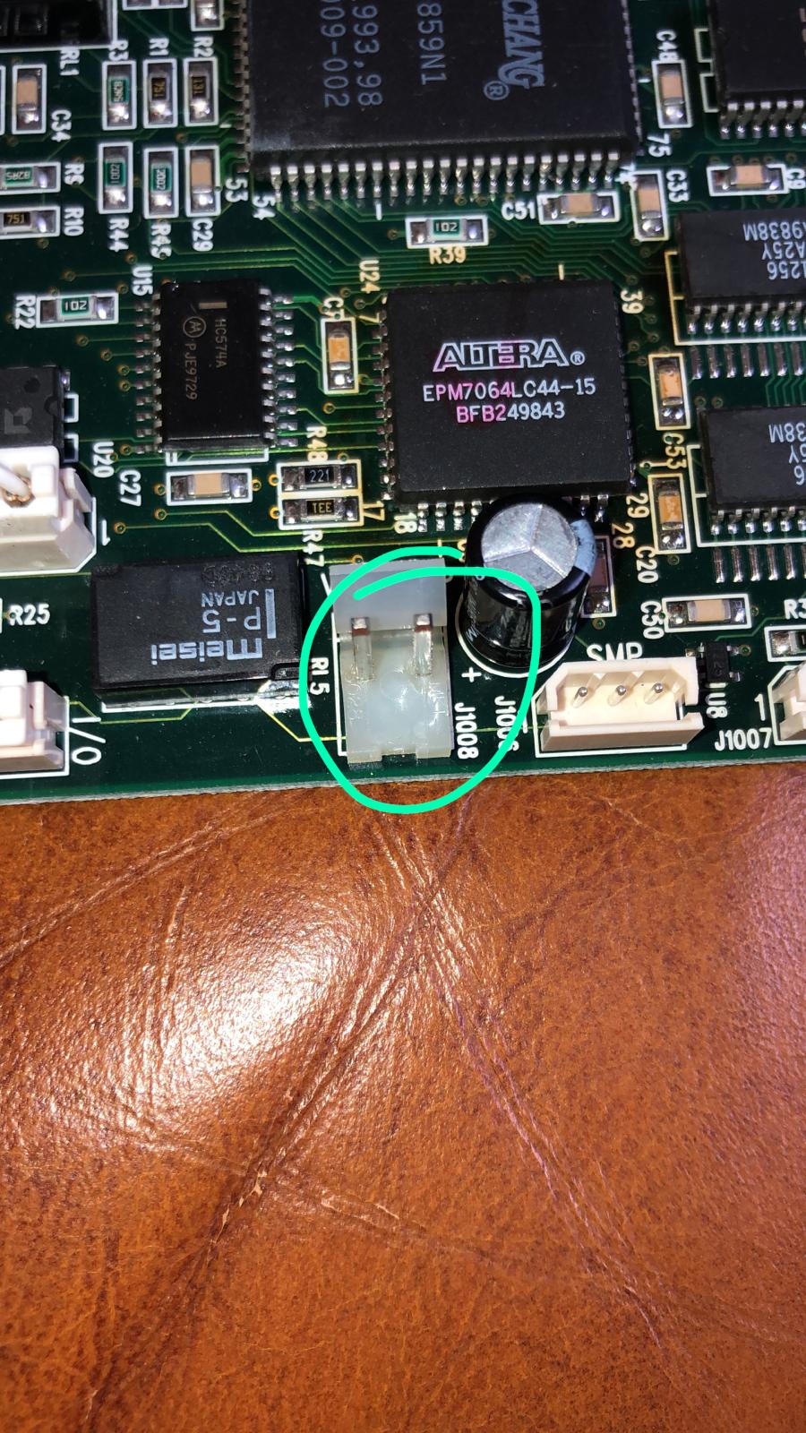
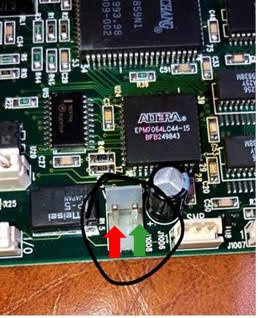
The next MAJOR and crucial step is to provide power to KDFX. In this case a
splice has to be made on two the wires coming off of the main power supply.
We provide a unique splicing tool that helps you tap into these wires, however
there is NO ROOM FOR ERROR.

Also before this procedure is done, you also need a voltmeter. You have to
measure the amount of power going to the display on the K2500. After you’ve
provided power to KDFX, you then need to use the Voltmeter to make the correct
adjustments to the power going to the display. If you don’t do this, the
display could become illegible.

There is also addition work and perhaps modifications to be done if you have
the sampler installed on your K2500.

Beyond the physical portion of the installation, a new BOOT Loader has to be
installed, then a new OS, then the procedure for installing objects has also
changed.

Again, I highly recommend you have a service center perform the installation
of KDFX. Please don’t attempt this yourself, as you could damage both KDFX
and your K2500.

Sincerely,

Mike Martin
Kurzweil

[On June 24, 1998, Mike posted again about this issue: ]

Kurzweilers,

Last week, I posted a recommendation to this list that you don’t attempt to
install KDFX yourselves and to have a service center do this installation.
Despite this recommendation, I have had NUMEROUS phone calls from customers of
my dealers, and email from people on this list who have potentially damaged
their K2500, KDFX or both.

By doing this installation yourself, you will VOID the warranty on the KDFX
and the K2500.

1 Like

Dear Coalheart,

thanks for your support, …I am for sure in a bad spot! :smiley:

The only reason is that even if the procedure is well described, some key points are missing and there is no feedback from other users or tech who have successfully completed the installation, there are also some exceptions and errors that can be understood only with a good knowledge of the system architecture and some basic electronics experience.

I have anyway finally received support from the Kurzweil Italian reseller at assistenza@generalsound.it, who reported the following:

"unfortunately these tools are no longer actively supported, the technical documentation is no longer available, therefore we had to request information directly from the factory.

We enclose the installation manual of the KDFX.

Anyway, as regards the power connector:

  • the red arrow (shown below) indicates the + 5Vdc line

  • the green arrow indicates the mass (GND)

image

installation manual available at the following link:Linkhttps://chrisarndt.de/files/kurzweil/Kurzweil%20K2500%20Rack%20and%20Keyboard%20-%20KDFX%20Installation%20Manual.pdf

I want to share my experience for those who might want to install on their own:

  1. installing the KDFX on a ENGINE MOTHERBOARD WITH REVISION G OR LATER AND NO J920 plug cable is possible only by connecting the DC power cable to power on the KDFX module as explained above.

  2. Attempting to power on the keyboard with the above revision number and without powering the kdfx will imply that the OS 302.KOS will correctly detect the new kdfx hardware (firmware test) and the keyboard will work but without the KDFX featrures.

  3. Attempting to install OS K25V404.KOS lowest revision enabled to drive the KDFX will produce the following error: “error bad flash rom chip or module is installed” probably due to missing power on KDFX.

I will report you as soon as possible once completed the installation.

@Red I’m in the middle of the KDFX installation and I’m stuck at the same place :wink:
Could you confirm that the polarity on this photo:
https://forums.syntaur.com/uploads/default/original/1X/6571c293b7baec64999402beb0cea74fb7cc9fbf.jpeg
(red marked +5V, on the left)
is correct indeed?

In my other K2500 unit, with a newer revision, there’s already a power cable connected to the motherboard. That connection to the motherboard (not the KDFX board) has the same bracket, but the +5V is on the right (and has a square soldering pad).

One of the soldering pads is a square and the other one is a circle.

On the motherboard the square one is +5V (connected to the pin 2 of the power supply) and is on the right, and on the KDFX board also the right one has a square pad.

This would indicate that the right pin (the one with the square pad) is positive, exactly the opposite of your drawing, so I’m confused.

The KDFX installation manual says that the gray wire should be connected to the +5V, white is ground.
Unfortunately, I don’t have the original gray/white cable with this connector. The manual says nothing about the polarity of the J1008