My issue appears to be related to the front left board. When it is disconnected at J4 the 5 volt rail is reading about 5.3VDC and the default boot piano sound is evident. The volume slider is working. When the front panel is reconnected the 5 volt rails drops to 2.4VDC and no sound is evident. On the assumption that this board is presenting a near short on the 5V, do you have any knowledge regarding the most likely component to be the culprit.There are several SMD chips and lots of Pull up circuits.
My first look at this problem showed a very hot 4.7 ohm resistor, when replaced all services worked. I am suspicious of the 470uF capacitors but they do not looked to damaged. Any pointers would be most appreciated.
from what you are saying there is a short on the front left board is pulling the rail down.
So now you have to locate it.
Something is possibly dumping current on to that resistor - resistors, in circuits, often soak up excess current.
I doubt its the large 470uf
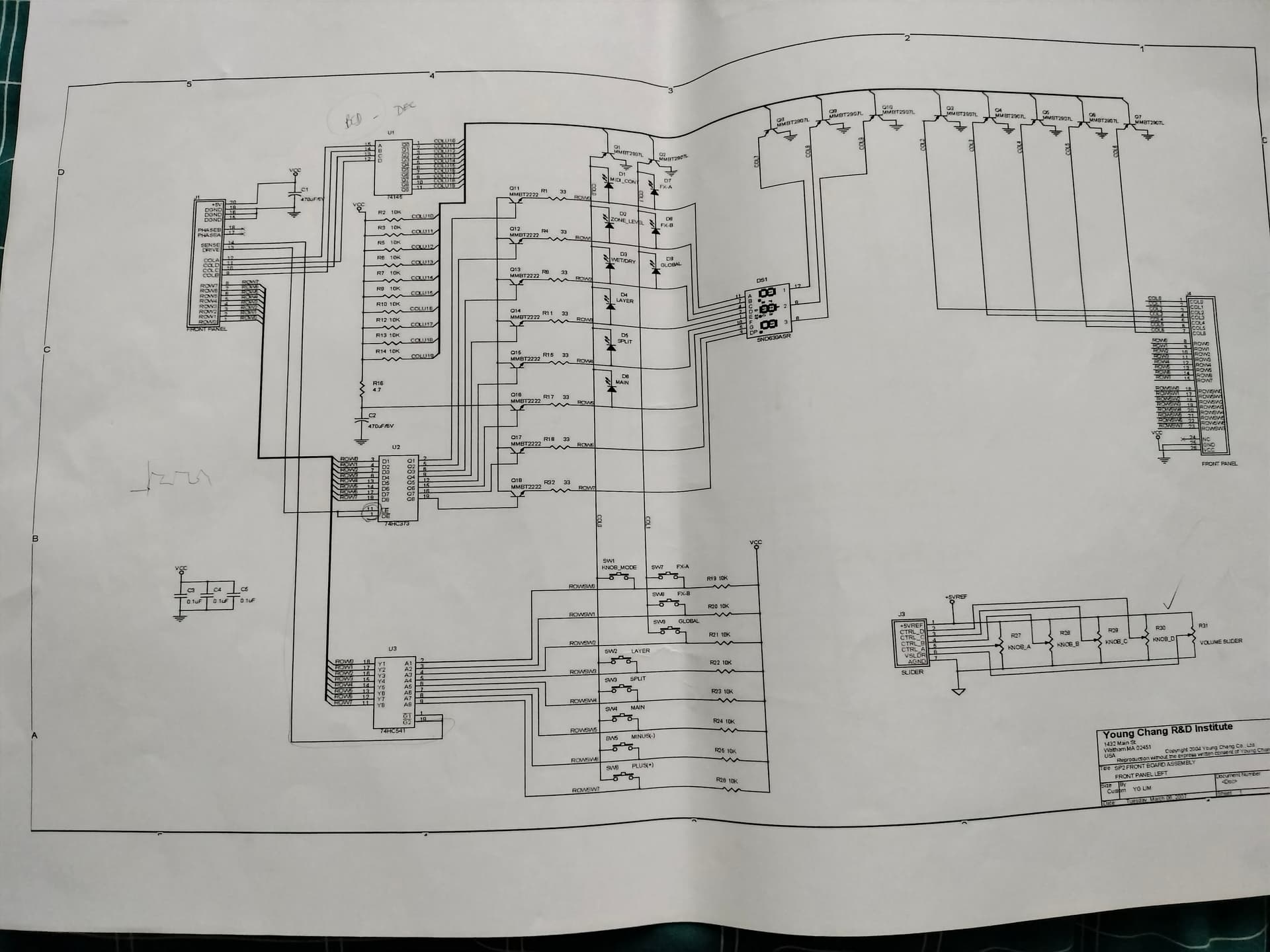
Do you have schematics?
Have you got a heatgun or ‘FLIR’ - these are quick ways to isolate shorts in ICs
Hi WE Robot.
Thanks for your response.
Yes I have schematics and heatgun. Sorry what is an FLIR.
hi
FLIR - thermal imaging
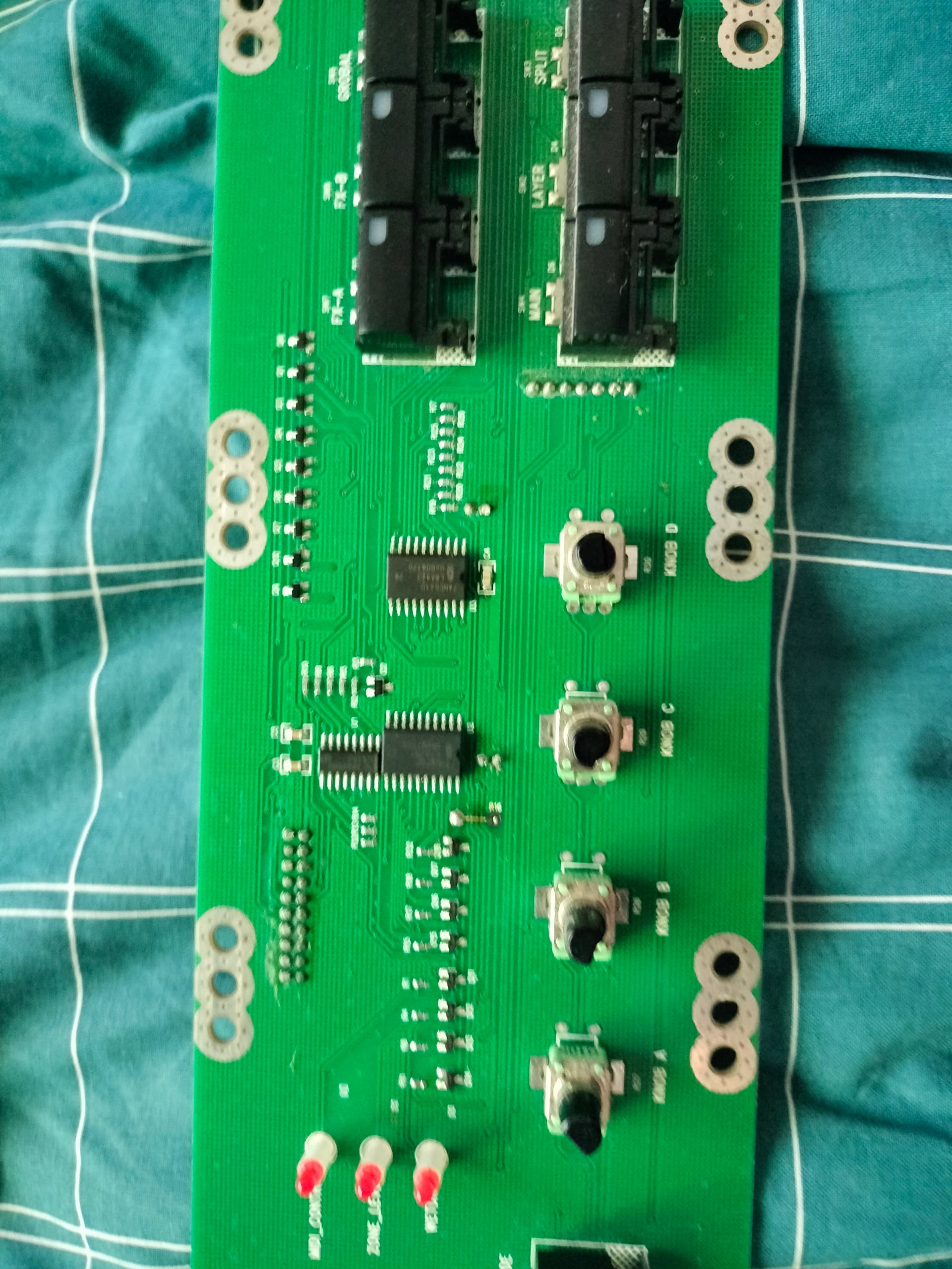
can you limit the schematic to the area in question and put it up here and also a photo of the circuit, again limited to the area in question.
Sure, do need the PCB powered up for the photo.
we_robot didn’t mean heatgun - that’s an Infrared Camera device where FLIR is a brand.
However - there is not much on that board apart from that C1 and 3 ICs, U1 BCD-Decimal, U2 Octal D-type latch and U3 Octal Buffer.
Just to eliminate - lift one leg of that C1 and try - it’s just a buffer cap after the cable and won’t break anything.
Seeing you got the board out - just measure across that 100uF cap with ohm meter and see hat you get …?
C1 is behaving like a Cap, starting at a low resistance and rising as it is charging.
In a past fault R16 4.7ohm current limit on the collectors of the row transistor drivers was severely overheating to the point of desoldering was replaced with higher wattage resistor. After that the kB became operational. All those SMD transistor collector are common to the 5V and they are downstream from R16. So have I got failed scanning due to a loss off incoming drive. The whole kB 5v is loaded . I will look at switching on those pins with front disconnected.
Hi Gents,
On your advice I lifted the leg on C1 470uF and the 7 segment display went through the boot sequence. Subsequently I replace it. kB is operating normally. Now the rebuild back.
I am thinking that maybe the previous failure was caused by as crook Cap.
Thanks for all your interest and advice.