Hi,
I am repairing a Matrix 6 PSU and have run into an issue.
The initial complaint was it was not turning on at all.
The xfmr was found, by myself, to be physically broken. It did not fail, just cracked at the terminals and was unable to be repaired.
I have replaced the damaged xfmr and DC PCB with a mean well PSU and a small center tapped 9VAC xfmr. Now it turns on,nhas output, and can be controlled with switches, just no VFD. This display was said to be working before.
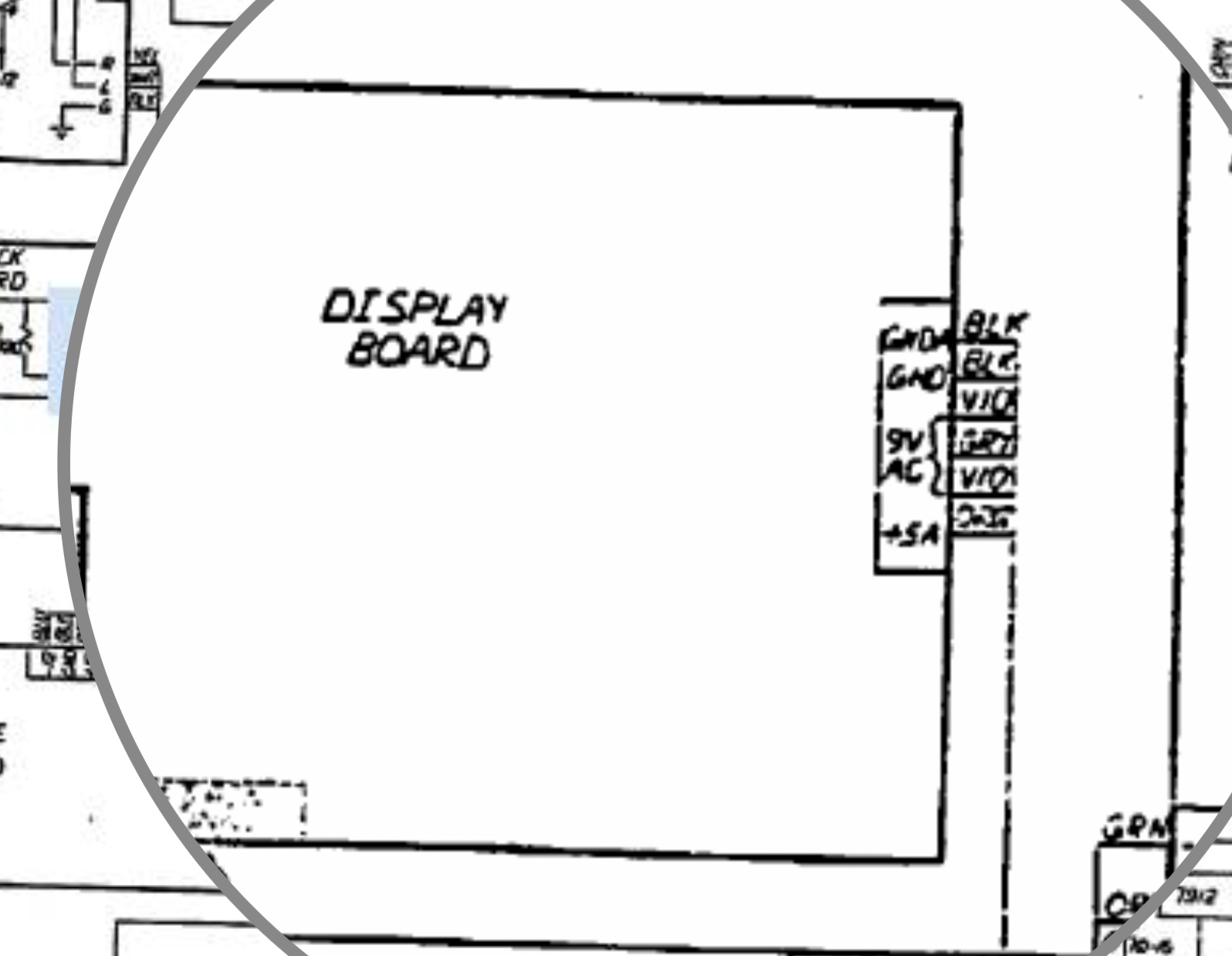
The display PCB schematic says it needs +5 and a 2x9VAC(J2, 5 and 3)
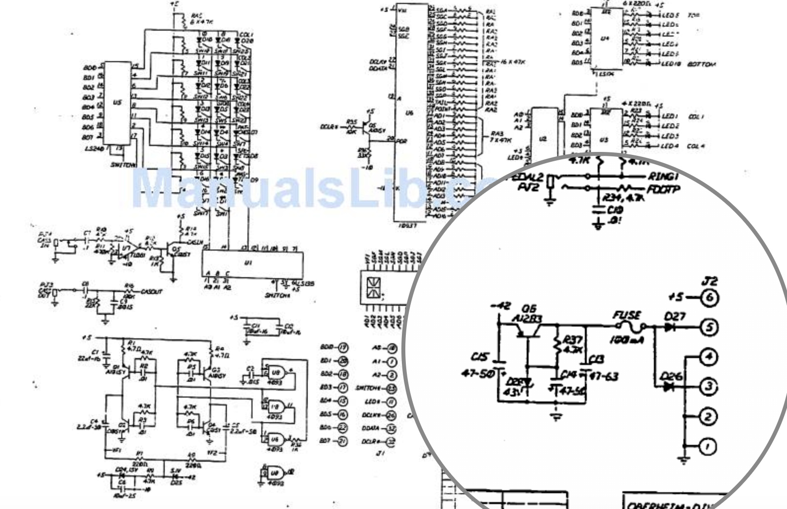
Issue is with the VFD not being supplied with the necessary -42VDC to operate correctly.
I can only measure -13VDC from the AC/DC circuit that is supplied by the 9VAC.
see pic attached.
I have replaced the 2SA1283, all components in this AC/DC circuit have been removed and tested. I have replaced U6. Removed the VFD (not tested) and not installed, the circuit VDC still reads -13VDC.
I have isolated this little circuit, output not connected to anything, and it still does not read the correct -42VDC, reads -13VDC
The 9VAC xfmr(120V in/dual 9VAC out, center tapped), is switched on with the 120VAC shared with new PSU.
I would like to make sure this -42 is correct before determining the VFD needs replacement.
Any thoughts?
Thanks
If you’re only getting -13V instead of -42, I’m betting that the display itself is fine, and just not getting enough juice. I think we have a Matrix 6 around (though I don’t know what shape it is in). I’ll try to poke around in there and get better educated.
Hi Sam
Yes, fuse is good, Have not attempted to apply more AC. I’ll try it and post what I find. It would be awesome and much appreciated to get AC readings on the violet leads from an original xfmr and DC readings from the incoming power circuit on the display board, if you are able to.
I set up a larger transformer to feed the circuit more AC.
I got to the necessary -42 VDC on the E of the A1283, it took 30VAC, not the 9VAC stated in the schematic.
VFD still did not turn on!
It was closing time so I did not investigate any further. Just wanted to post an update.
It looks like the violet leads have a gray center tap. Measuring at the display board, each violet to gray is 42.7 VAC, with violet to violet measuring 85VAC.
Hi Sam,
Are you able to verify that the -42 VDC @ C15 is correct and what is needed to drive the display board?
I’m running into issues finding a replacement transformer with that spec and i am looking to supply the DC voltage with another small power supply and by pass that small rectifier circuit.
Hi all,
I verified that the display IS working in another Matrix 6 chassis with an original power supply.
I found a DC psu that could supply -42VDC(Meanwell RS-15-48). I removed D27/26 and connected -V @ pin 5 and +V @ pin 4. When on, LEDs are functioning and I read correct voltages everywhere, but VFD is not lighting up!! Although, when decreasing AC to off, through a variac, the VFD wil flash for a second. When turning on with variac, it does not flash.
Both new psu’s (Meanwell RQ-50B/RS-15-48) are not connected to AC ground. Any ideas of why this might be happening and if I going about powering this up correctly?
Thanks
Mateo
The display needs to see 85VAC across the violet wires, with a center tap on the gray wire. It sounds like you are feeding it DC instead of AC. I don’t have a Matrix 6 handy at the moment, but I’m just going off of the fact that I measured AC voltages in my previous post.