I have a moog prodigy that is in constant sustain. If a key is pressed, it will hold the note indefinitely until another key is pressed. Everything else on it works perfectly.
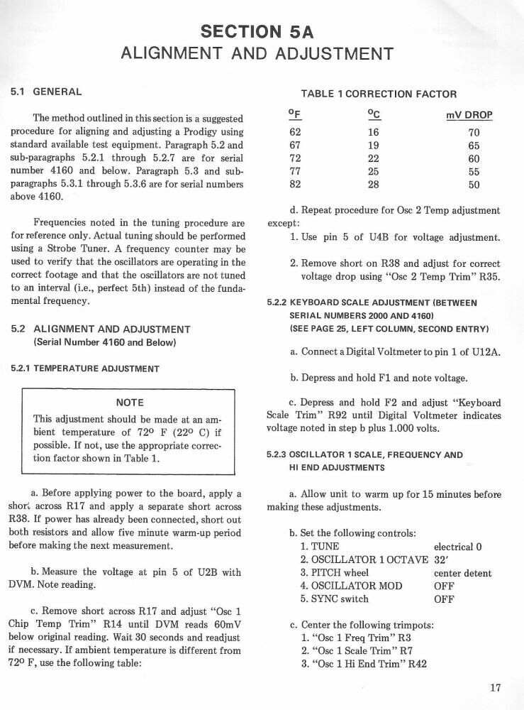
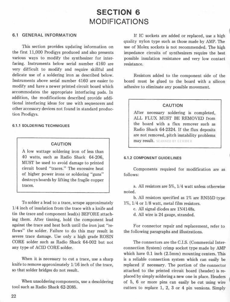
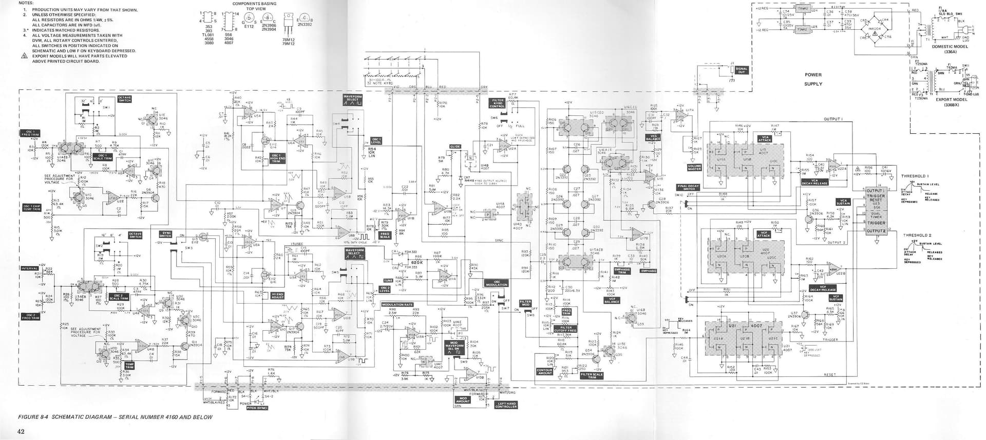
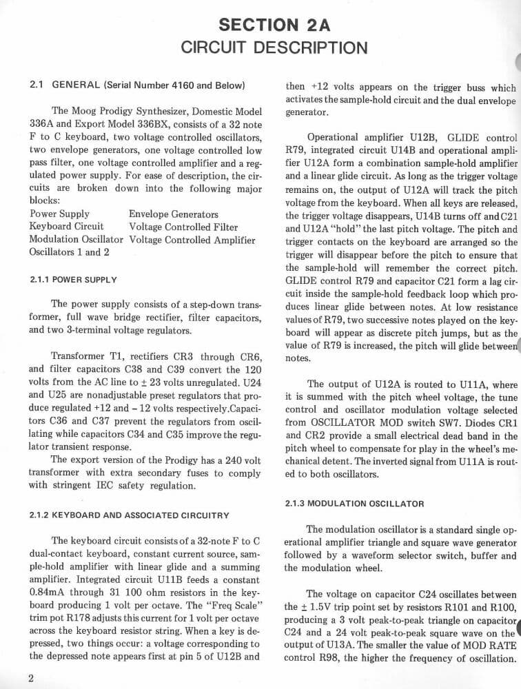
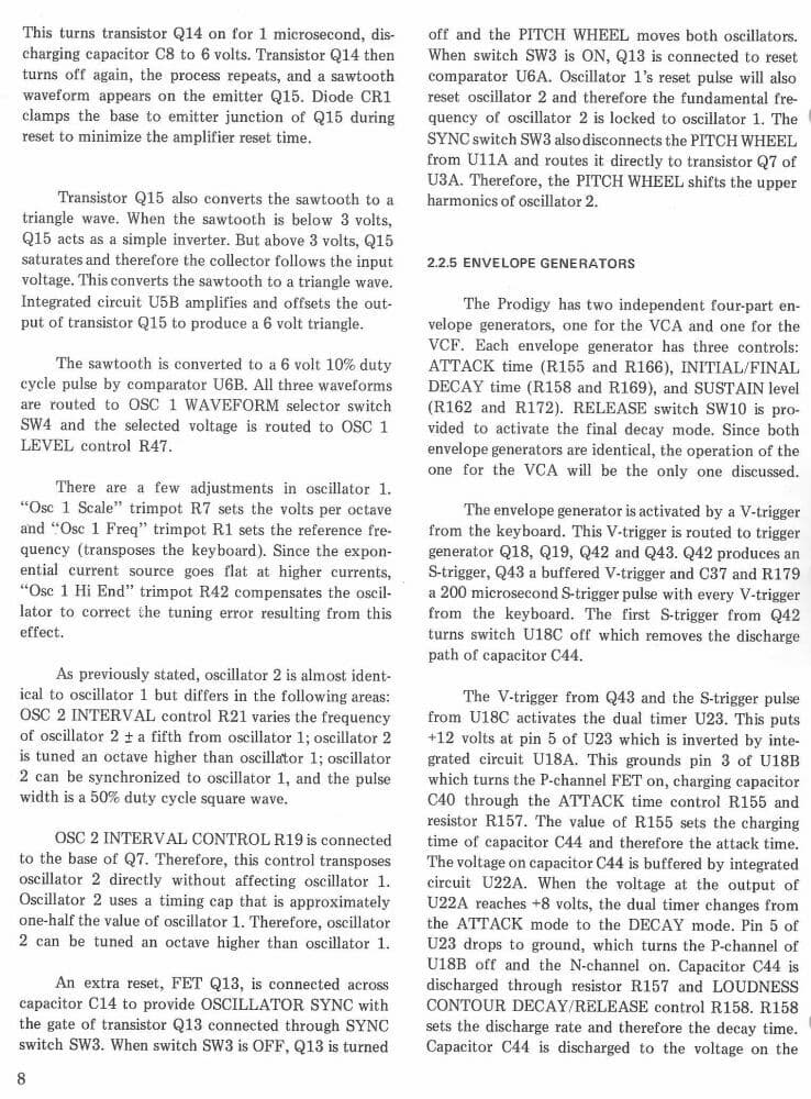
Assuming that keyboard contact wires are not getting hung up on the 12 volt keyboard trigger buss bar, I would suspect the key trigger sample and hold circuit, made up of a 4007 (schematic label U14B) and a LF353 (label U12A). It’s described on page 2 of this excerpt from the service manual. http://www.midimanuals.com/manuals/moog/prodigy/service_manual/moog_prodigy_service_manual.pdf
I confirm @armillary
The 4007 is known to fail. It would be my first guess too.
If the tone is present even after switching on, without pressing a key, then U12A might be the cause. If you first have to press a key to evoke the endles sustain then the U12A is fine.
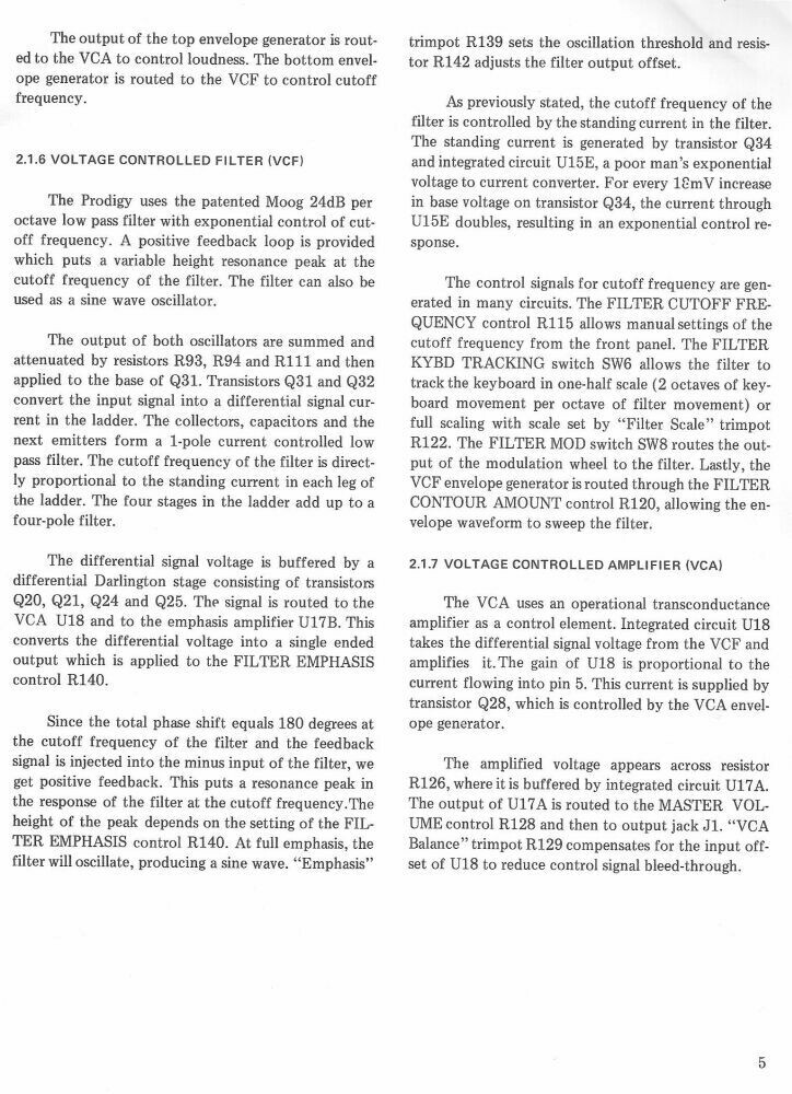
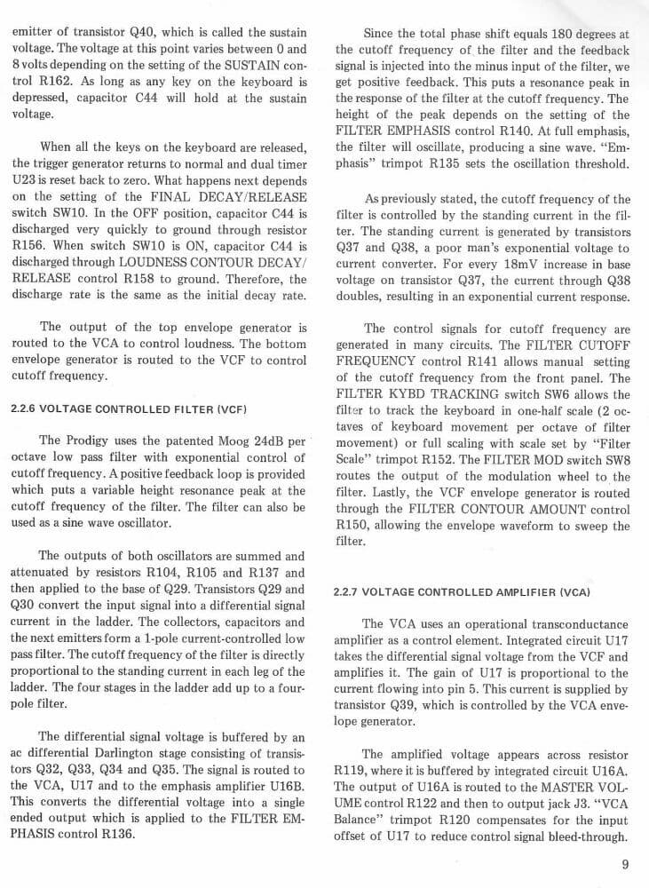
Is the hanging sustain for both envelopes? If yes → U23 (NE556) is a suspect too.
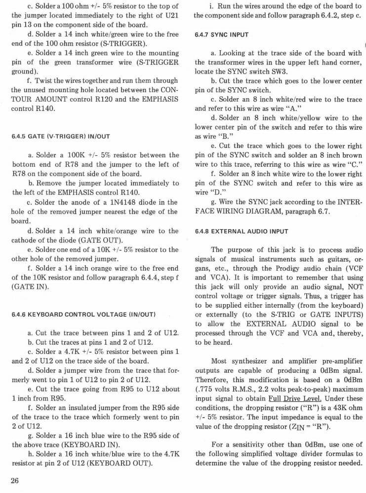
If only one: check the 4007 of the envelope (U19 / U20 respectively)
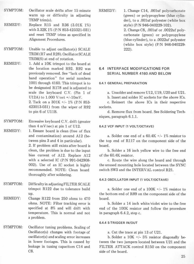
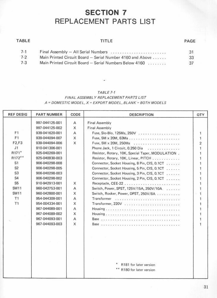
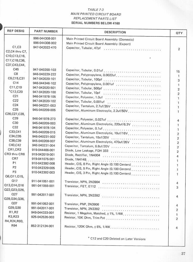
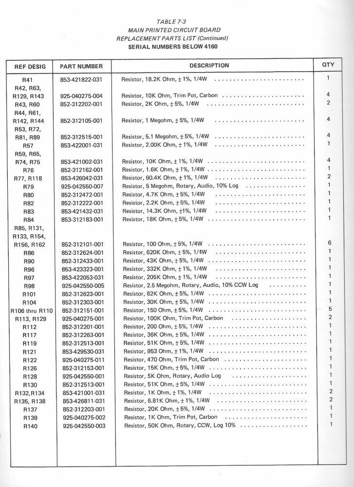
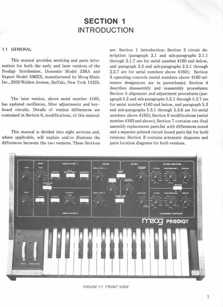
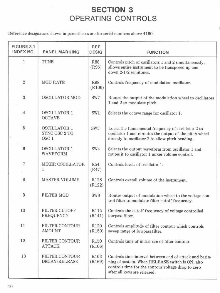
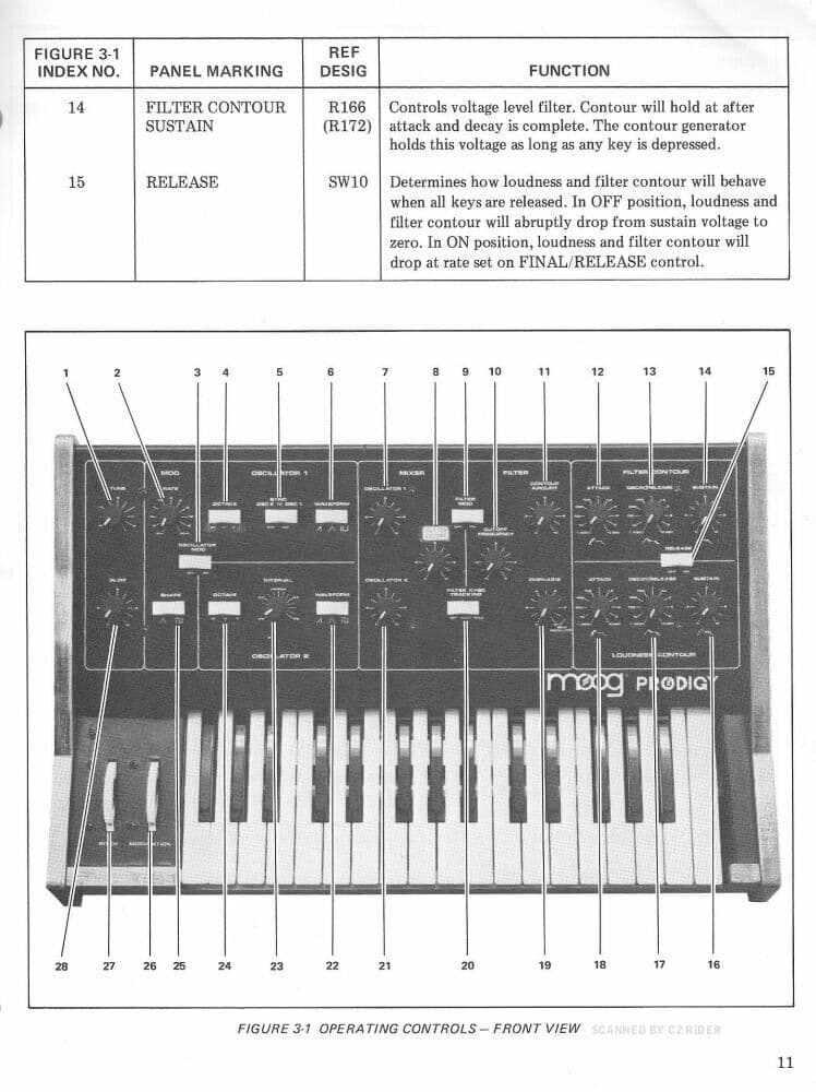
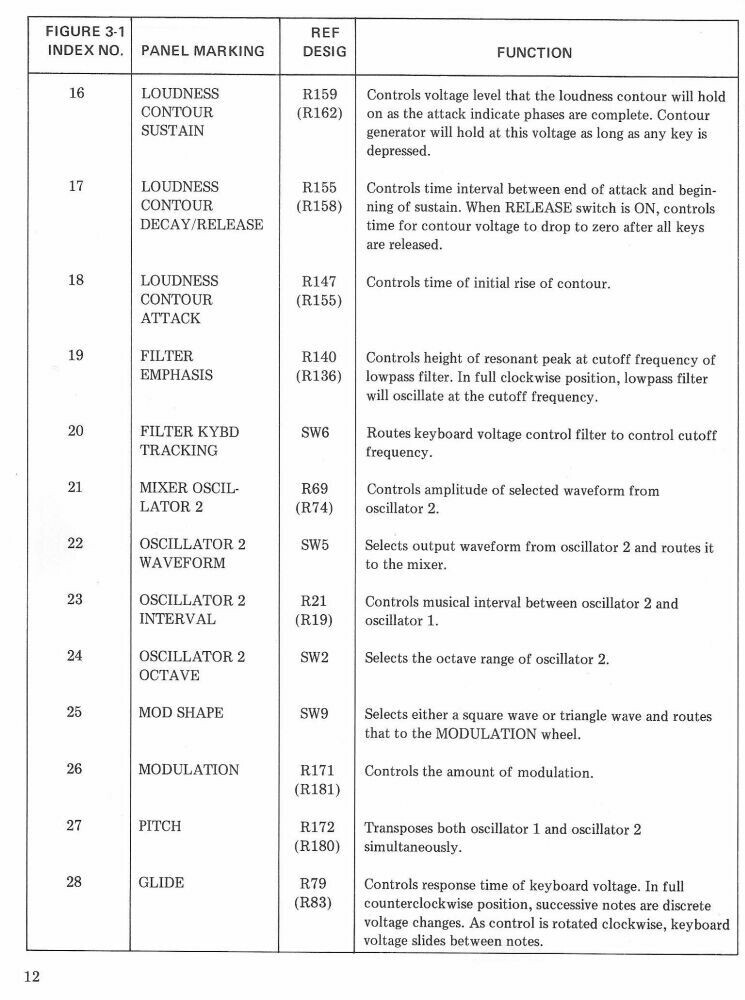
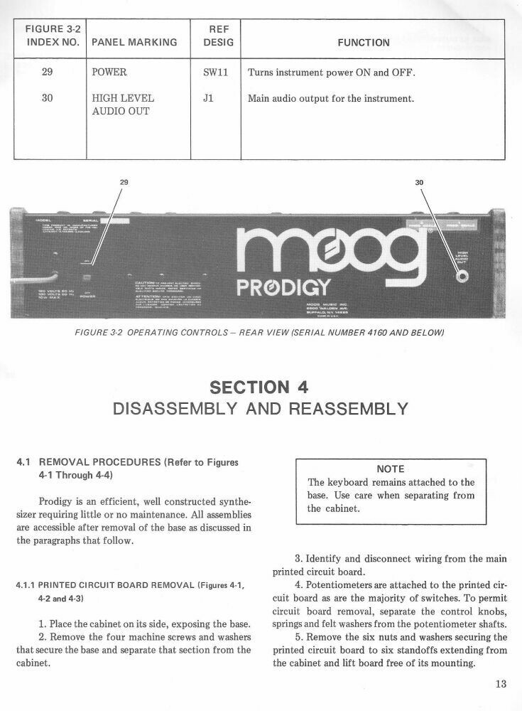
What’s the approximate serial number of your Prodigy? There was a mod for hanging sustain for the early models below 4160.
Thank you for all of your help so far. My S/N is 7095.
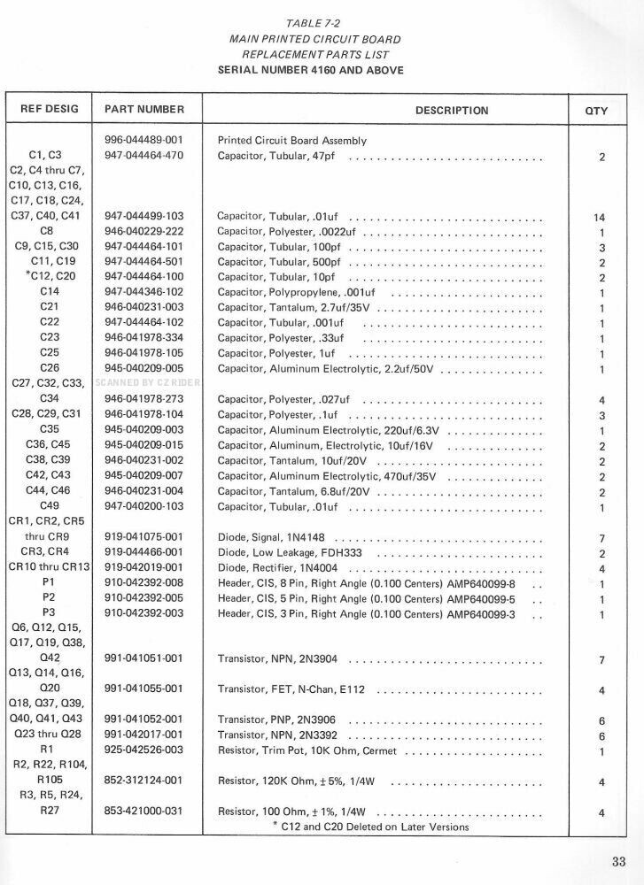
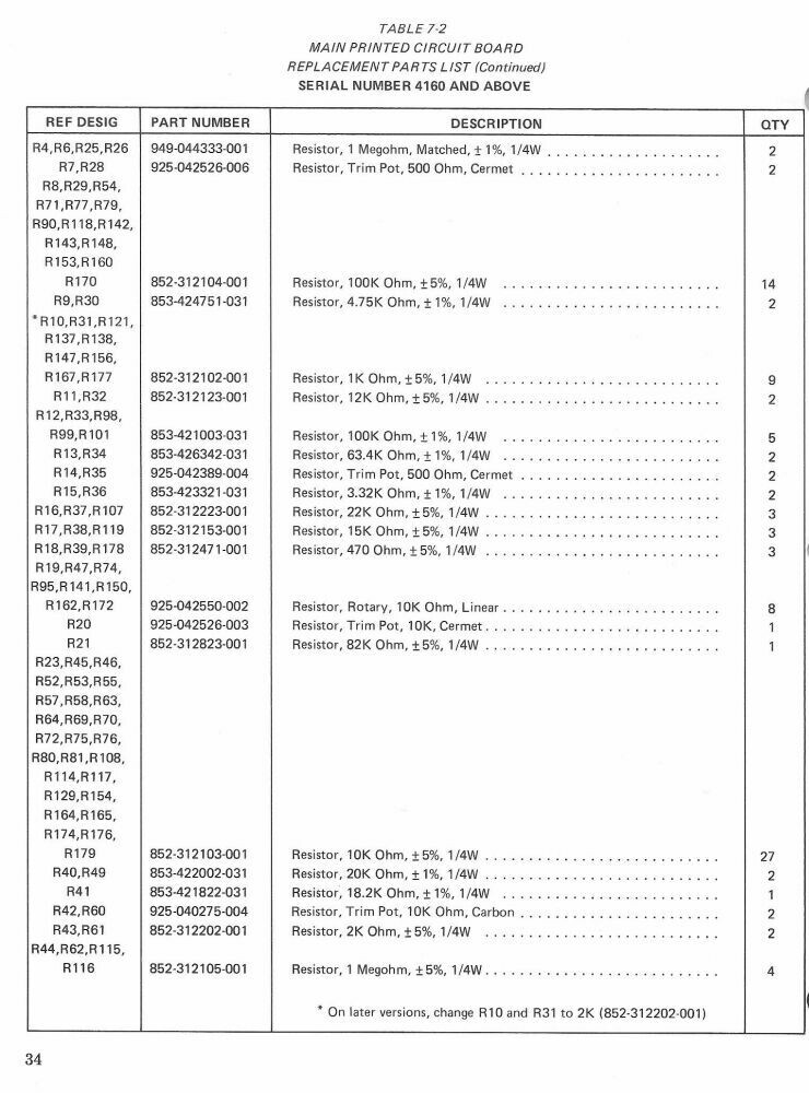
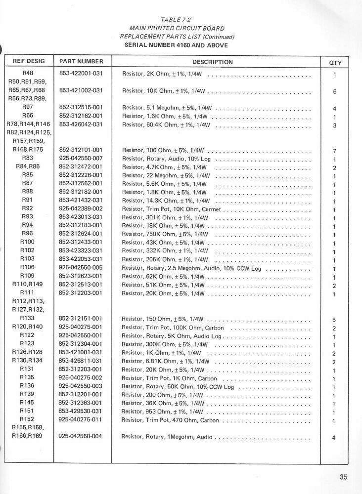
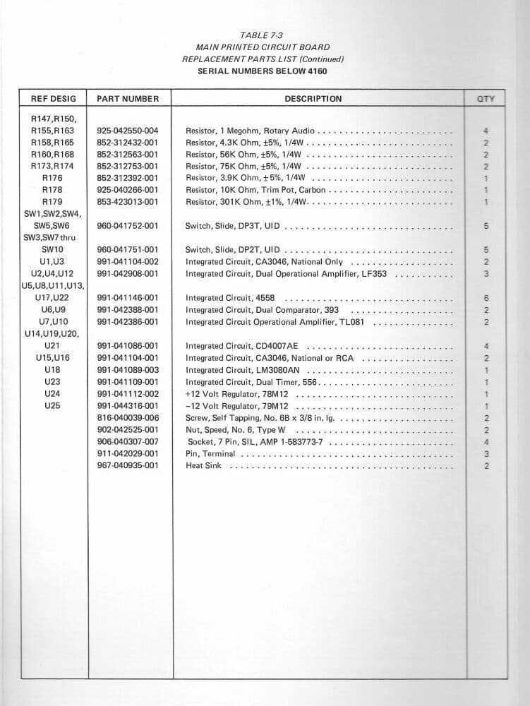
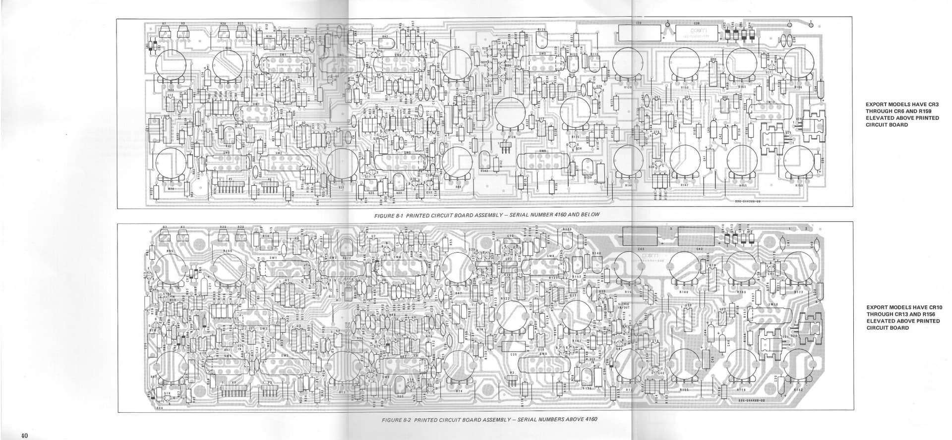
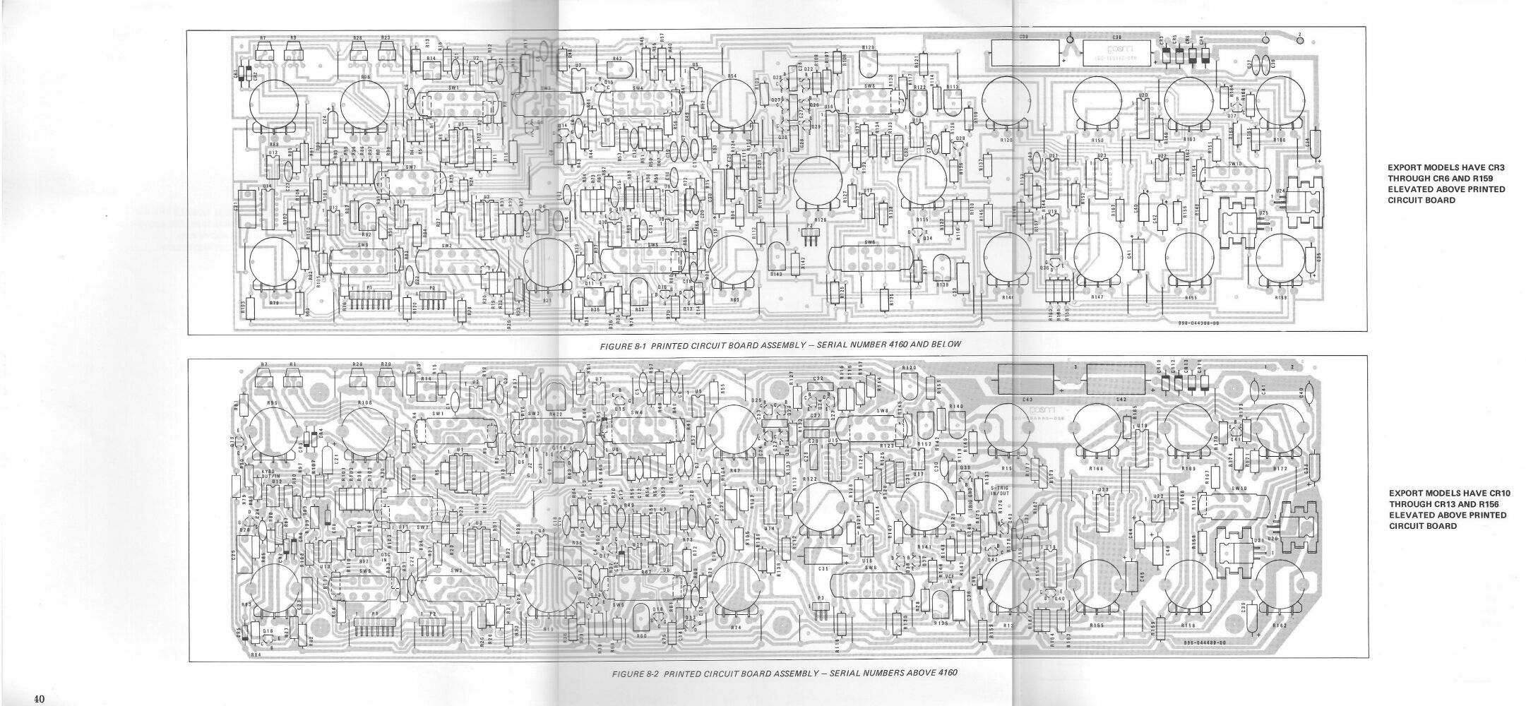
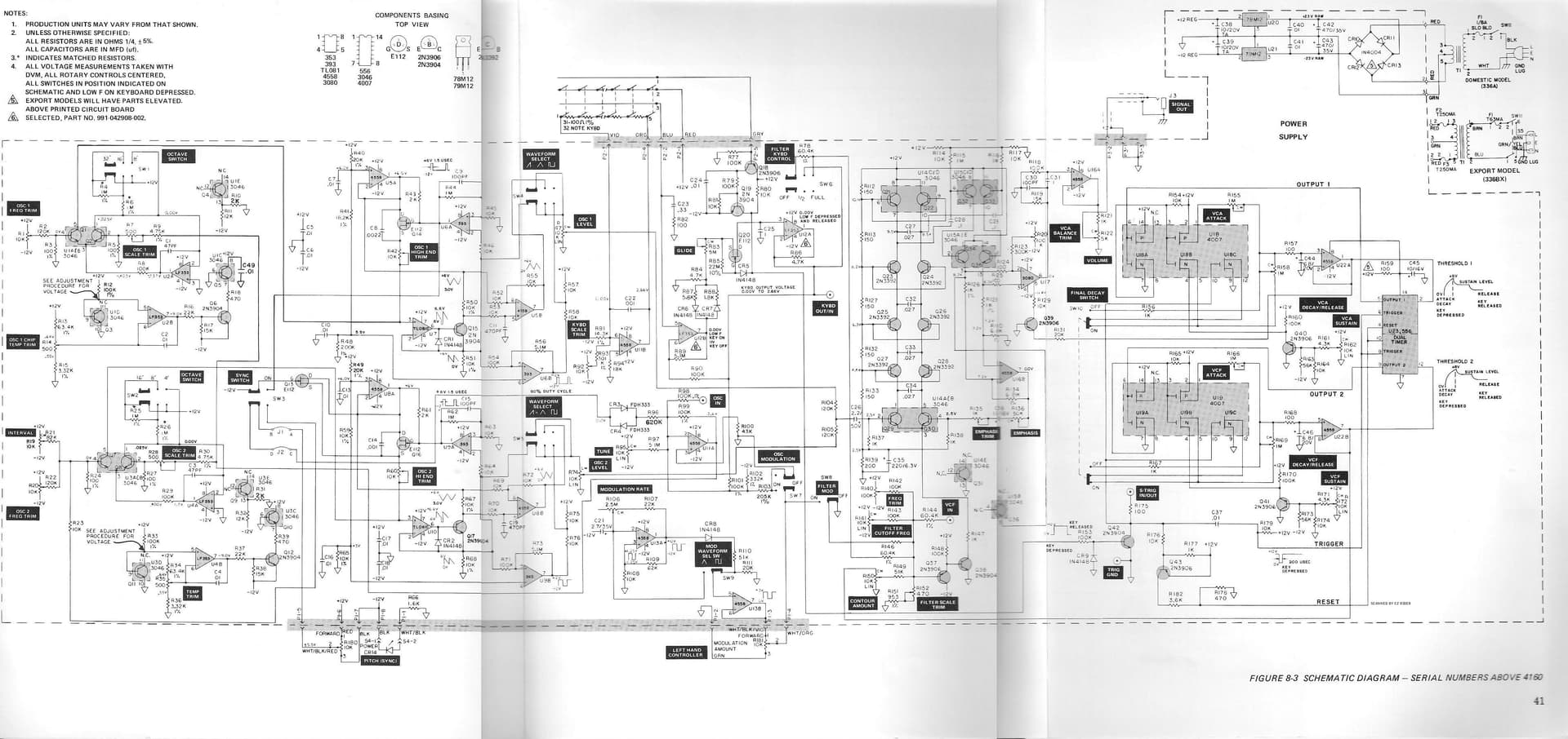
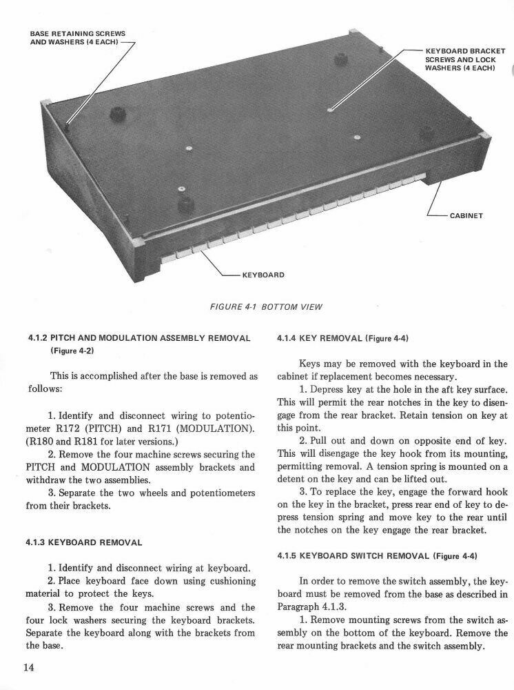
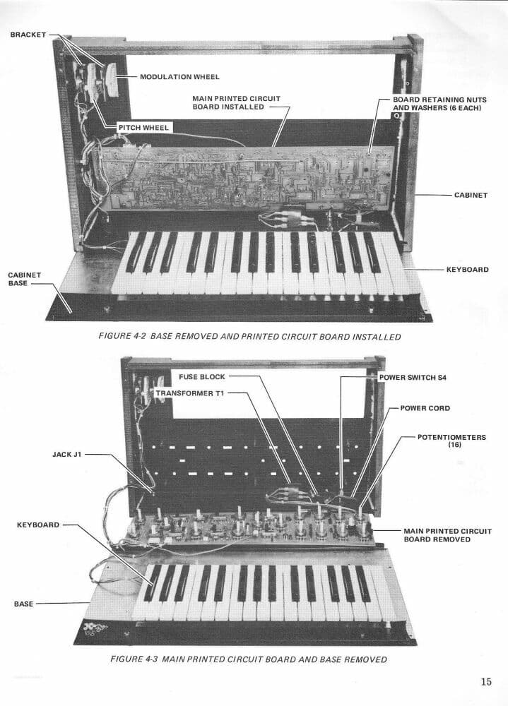
Ok, we should have asked the serial number before looking at schematics. There are two schematics, one for serial number 4160 and below, and one for serial numbers above 4160. Our comments about 4007 U14B were looking at the schematic for 4160 and below. The good news is, for serial numbers above 4160, Moog redesigned the printed circuit board and replaced that 14-pin 4007 chip (U14) with individual components. So on your serial number 7095, the suspect component is schematic label Q20, which is an N-channel FET transistor of type E112. (Syntaur actually has these in stock.) The other suspect part that we referred to as U12A in the old schematic is still U12A in the new schematic, and it is still a LF353, a dual op-amp DIP-8 IC. One more thing before I forget, these sample-and-hold circuits are very sensitive to any residual solder flux. It can cause the problem you’re having. It’s possible that when your Prodigy was assembled at the factory they didn’t do a good enough job using flux remover to clean up all flux residue around these components. It would be worth a try to use flux remover on a q-tip to mop up the area around Q20 and U12 to see if that fixes the problem. And if you do end up replacing anything, be sure to use the flux remover after.
This make so much sense now. The schematics weren’t lining up but now everything is so clear. Thank you for your insight. I will keep you posted on my fix! Thank you!
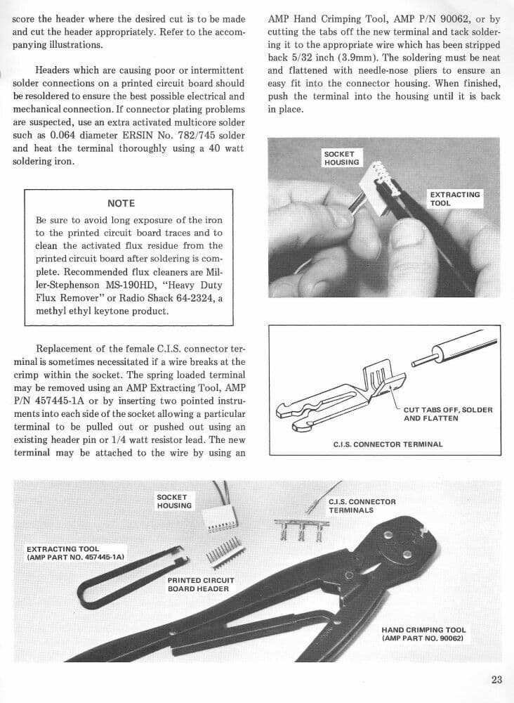
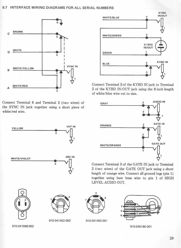
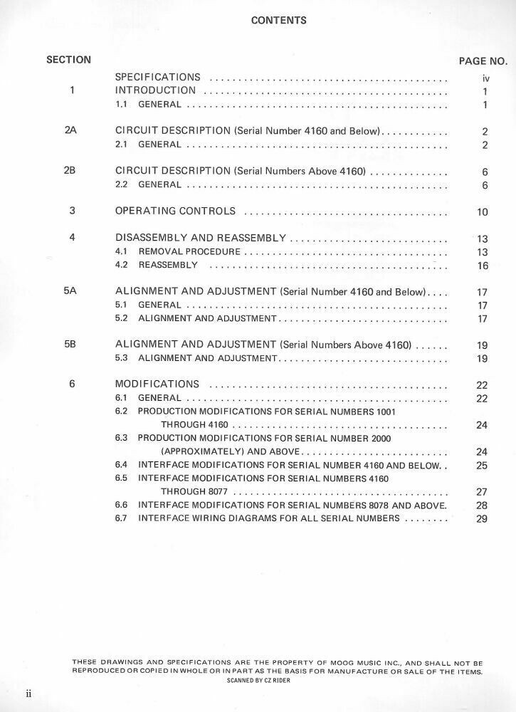
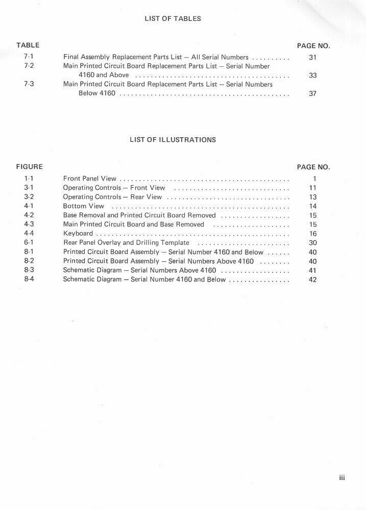
Great! I have the scanned pages of a service manual for the Prodigy that I got about 10 years ago. It’s about 45 pages and has the old and new schematics and images of both PCBs. If you don’t have that I can post it.
I would love to have that resource. Thank you!


Thank you for everyone’s help on this! I was able to fix it. As I was cleaning the solder joints I realized a joint was broken. I recapped that joint and cleaned it with flux cleaner and it worked beautifully!!! Thank you again for your help!
Excellent! It might have been a cold solder joint from the factory. Do you recall which component it was that had the cracked joint? Was it Q20 or U12, or something else? And I’ll post the last few jpegs of the service manual so you’ll have the complete set.