Hi, Synth techs,
I picked up a Motif XS that does not boot. When I opened it I found a few parts blown,
D901
FT901
IC903
I also changed some electrolitics to be safe in the same area. When I powered it up I measured the voltage rails and all seems ok. All I get is the backlight on the display and it does not boot. At this point I am really lost I have no idea what to look at. If anyone has any suggestions , it would greatly be appreciated. Also if you need the service manual message me.
Regards !
OH ya , one other thing Im missing the bender / slider assembly completly. If you have one message me please.
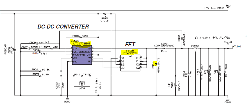
SO … you are saying you replaced these components (yellow in the pic below) ?!?
How were they blown … split open, cracked etc etc ???
After your repair - have you got the 3.3VD ?
The diode was open and someone else had worked on it before me. The FET was missing so i replaced it and I changed IC 903 as I had one in stock.
Tonight I went over the rails again and wherever there is suppose to be 3.3v I end up with 4.7v. All other voltages are dead on in the schematic on page DM 2/4 Power Supply(section 9 / K)… Any suggestions? Ill get back on it Sunday…
Thanks for your time.
Garry
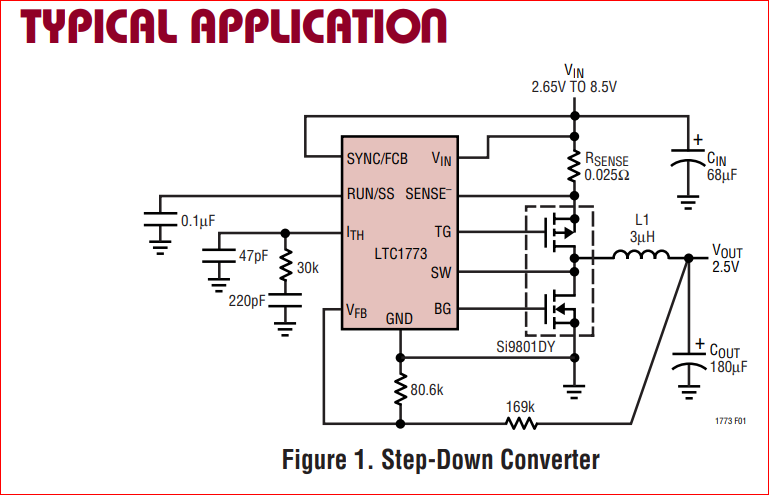
Look at datasheet how it’s working.
Is the feedback circuit into pin 4 (Vfb) on IC903 intact?
(3.3VDC / (R911 + (R904 || R905))) * (R904 || R905) =
(3.3VDC / 94.2) * 22.7
I am trying to ascertain whether the components on the 3.3VD are capable of handling 4.7V - which is basically Vin minus sense of IC903.
I must say this is a very difficult board to work on. I had to remove the components to test properly ,all went well and I can say the feedback circuit for IC 903 is ok and intact. while I was at it I verified C915 also and D902. I still can’t figure why I am getting 4.7V? I tried readings with another meter and exactly the same. I looked at it with my scope and no ripple… Well a little each day but its not an easy one for sure.
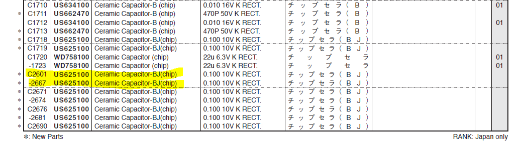
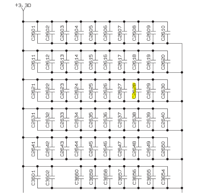
Ahhh now it’s getting interesting. I have no idea why but, I put the board under my microscope and on the back side I found C2628 (service manual pg 85) cracked in two. Looks like impact and not a circuit problem. There is one problem I can’t measure the SMD cap and I can’t find the part value in the service manual. Im going to have to get thicker glasses…
I have spent hours looking , Dam can’t find it !
Any help would be appreciated.
Cheers
This is the pars list for MOTIF XS
I can’t see that cap being a problem - is just a noise eliminator - just remove it for the time being … that doesn’t hurt it
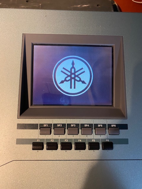
Well, I hate to disagree with you but i installed a new 0.1uf (104) cap ( Not sure about my value? ) in the location of C2628 and as you can see I have a partial boot… It freezes on that screen. I did measure the 3.3v line and I still have 4.7v, thats a mystery still.
Wernersaurus, I want you to know Your time is super appreciated. Ill get back at it later tonight… LOL I work better at night…
If anyone has any ideas please jump in, don’t be shy. I can use any help I can get.
Have a great day/ evening
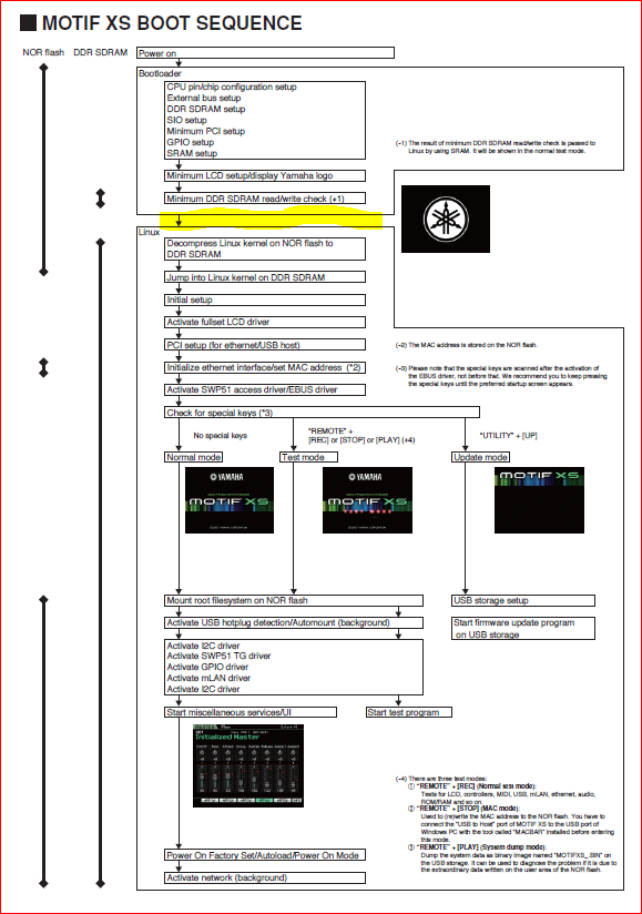
Seems you are stuck on Linux Load …
I wonder if the SD Ram could be bad. Not knowning its history does not help and the person who I purchased it from did not tell me there was another person in there before me. So you know how that goes.
All he told me is he tried to install some sims and it did not work. I should have put a bible infront of him and asked him if that is the truth, and nothing but the whold truth…
Whats your guess on the 4.7V ( should be 3.3v )? The reason I find that strange is because all other voltages are dead on as per the service manual.
1 Like
That 4.7V …the only thing I could think of is the bottom FET not working - either not turning on/off by the switcher or the BG leg of the switcher not working.
If the top FET is not working then Out would be 0V. If the top FET is shorted then Out would be In. If the switcher is not working Out would be 0V.
If the switcher is working but the bottom FET is faulty then Out would continually charge C922 but never dis-charge it to stabalize Out to the designated voltage given by R911 / R094 || R905
Is there a way I could look at that with a scope? A little over my head.
Or for what it would cost ill just swap out the Ic’s. The more I look at this it really looks and smells like a supply problem. It’s a very difficult board to work on, being such small surfacemount components.
off to sleep back tomorrow.
Night
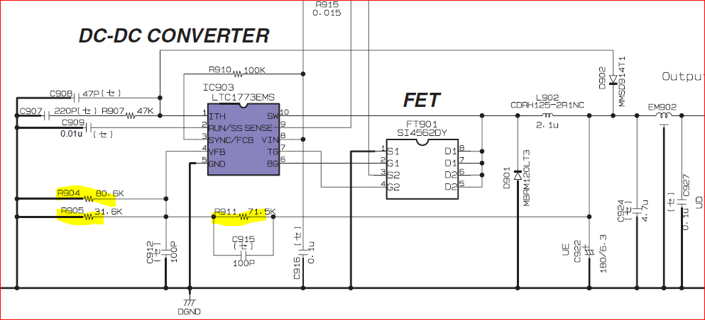
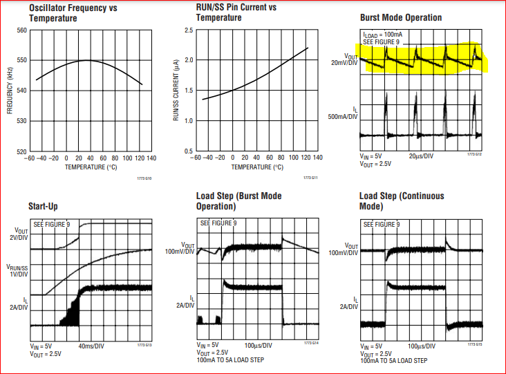
You should be able to see something like in the pic below (yellow) BEFORE the coil (ie Cathode of D901) and also the switch pulses on either of the Gate legs if the Dual FET (ie G1 and G1) whereas the pulses being offset between the two (if you have dual trace scope set each input to one of the Gates)
I think I might have it thanks to you my friend. When I ordered IC903 #LTC1773EMS
that is not what I got. I recieved LTC1733EMS !
I was looking at my orderslips and I just noticed it. Holy Crapo…
Just ordered the correct one.
Cheers and Good evening, im off.
Ha !!!
Battery charger … that definitely won’t do the trick !!
Good find !!!
Ill be back with a report once I recieve the part.
I told the distributor about there error and told them I expect compensation and free shipping. They will send me 5pcs $11 ea.
(Oh yea, or I would mention there name in the forum ,  )
)

Well, Like they say its not over ,until it’s over. I installed the correct IC 903 and the Fet FT901 went up in white smoke. I verified that all was installed correctly and it was.
Being a bit tired today, Ill replace the Fet tomorrow. What im wondering is could that wrong IC have damaged the FET? Hummm. F$*$$&@^
When I powered ,even with a Dim bulb it pulled a full amp or more and the party was over. Dam.
Today is a HAPPY day !
1st thank you so much for your suport Sir wernersaurus
I replaced IC 903 and FT901 this morning . The Motif XS booted up !

On to the next project.
1 Like