Roland 707 – IC35 Chip replacement (HKA Design Mod)
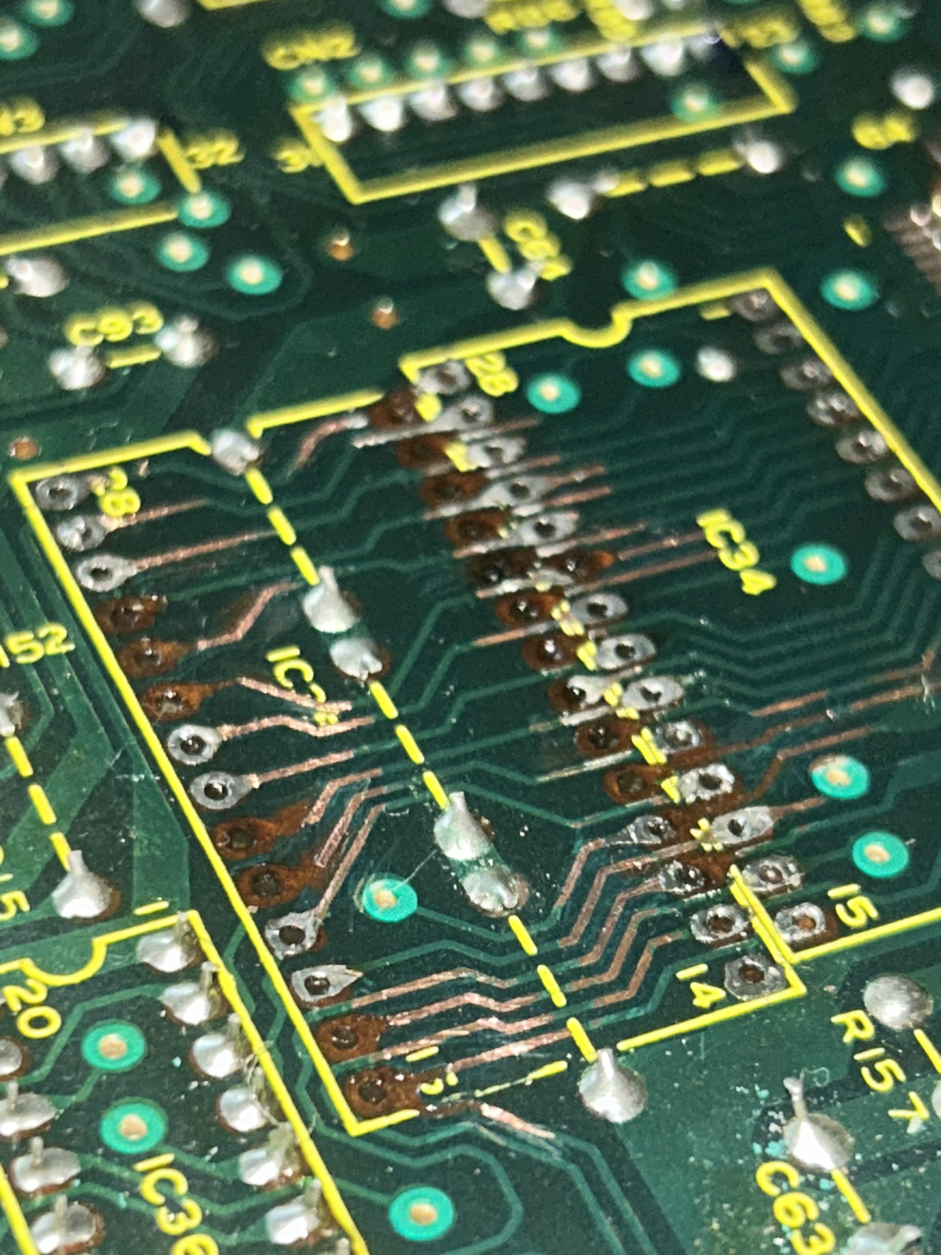
Someone did the chip replacement for me and did a bad job at it. I decided to take matters into my own hands, and retrace the lost traces that lead up to the pins of this chip. As you can see on the pictures I added some traces that lead up to the pins of the IC35 are really close to one another. My plan is to get some double sided copper tape into the trace channels making sure that ones close together will not touch eachother, and stick new replacement pads (picture attached) on top, to be able to re solder all of these traces.
I have some concerns though regarding how well my solution will work. Will this cooper tape loose its adhesive properties and lead to new lifted traces as im soldering or over time? Am i right about putting copper tape first and adding replacement pads on top ? What should I add to the fix once im done with it to protect it from environmental factors and possibly lifting back up? Does someone recommend a specific brand of replacement pads ?
it’s my first time implementing this fix, and I wanted to seek out advice from experts before hand on best practices.
I suspect the adhesive on the copper tape will not hold up at soldering temperatures. But new pads can be attached with a high temperature epoxy.
Another way to fix this is with jumper wires. You would solder the chip in to the remaining pads. Then solder wire from each component leg without a pad to the nearby exposed trace or all the way to the pad of another component it connects to. I’d recommend using pretty thin wire, like 30 AWG. You can glue the wires to the board when you are done to secure them in place.
Check this link out for more info on both methods..
Thank you kindly for your response:
I like the first fix you proposed, as I want to avoid using jumping wires. I actually want to retrace.
So going back to your first solution, you are saying I should lightly apply some high temperature epoxy on these traces then stick the new pads on top, wait a few hours or so for it to dry fully. And then when i’ll be applying solder on the new pads to complete the traces (since it’s a high temperature epoxy) epoxy will stay intact (of course only if i spend 1 to 2 seconds max soldering each pin)?
Any advice on how much epoxy should I apply ? especially near the pin wholes where the chip comes in ? Will too much epoxy ruin something for me ? Also what if a tiny bit of epoxy leaks over to the top side of the new pads, will that be a problem ?
Excuse my excessive questions, I’m trying to do this perfectly as I love my 707
Thank you kindly for your response:
I read somewhere that using jumper wires introduces noise, and i’m thinking that i want to avoid doing that since this chip is crucial to the sound generation system of the 707, I want my instruments to sound as clean as possible. do you think that adding new pads might also introduce noise ?
So here is what I’ve done. From my pictures, it might seems like some lines might be slightly touching each other especially on the right side of the board. My multimeter did pass the check every time I would check for continuity, and also checking if pins that weren’t supposed to be in contact, actually were. None of them showed me bridging between pins, but when i plugged the 707 back on, all of my drum kits were distorted. I am suspecting some bridging might actually be happening and that my multimeter, isn’t sensitive enough to detect it. what do you think ?
I am using all the right tools, magnifying glasses, a ton of flux etc..
thanks
One idea is If you stick a IC socket into the place where the IC is missing, this will give you some posts to solder to. The IC can then just sit in the socket.