Did you check to make sure none of it’s capacitors is leaking fluid or bulging in size? That’s what usually causes power supplies to die. You may need to replace it’s capacitors if you are familiar with soldering. It’s a fairly simple process. Just make sure the new replacement capacitors are the correct power rating or higher. That’s what to check for first. Also check the machine to make sure it doesn’t have a burnt out fuse. Hope this helps
I’ve manually powered on the board only via the pins and the current jumps up and down using around 200mA. I don’t think it’s the power button in that case.
The caps are polymer and not bulging. Can’t see anything obviously wrong with it. Can’t see a fuse either, but current draw on xpwr-sw going low suggests power is getting to the voltage regulator.
I’ve only got schematics for the jack and button/led panel board, so struggling a little.
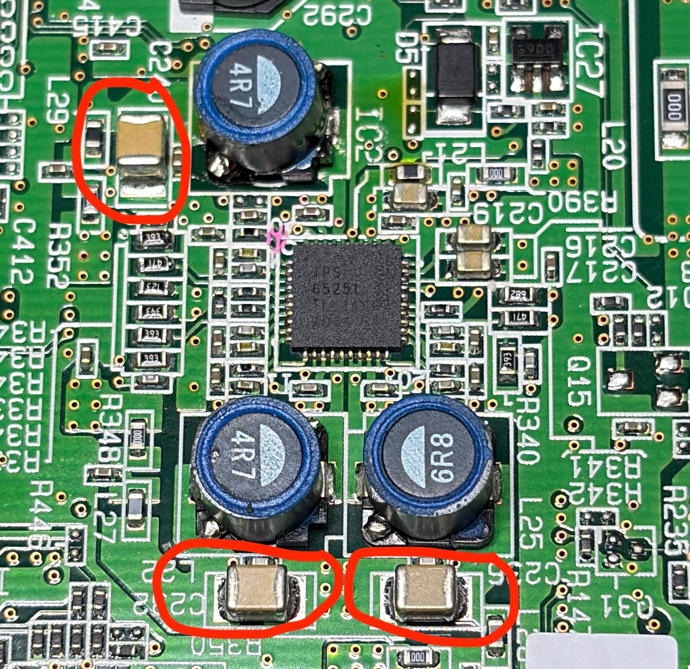
I did notice it has a TI TPS65251 triple buck regulator, so will look at this first. Google AI suggests it’s the power regulation.
I need to check PGOOD signal and 3 rails of 5v, 3.3v and 1.2v next.
OK, so there’s a short on the LX3 output of the TPS65251 triple rail regulator. The 3.3v rail to be precise.
PGOOD was bad, so I checked each rail voltage and then resistance.
LX3 measures 17R and with the inductor removed, still 17R. So I know that the chip is at fault, not the down leg circuit. The other rails are around 170K
I’ve ordered another chip which will take a week to arrive.
Just a few other things to check, but hopefully this fixes the issue.
Google AI is pretty good at this stuff! Gives some really useful tips to help repair circuitry.
Check Power Adapter: The most common cause is a faulty power adapter. Even if it reads 12V, it may not hold the necessary current under load. A flickering or low-power supply can cause this issue.
Try another power adapter.
Perform Factory Reset:
Turn off the FP-10.
Hold down the VOLUME (right) and FUNCTION buttons.
Press the POWER button.
Release the POWER button but keep holding VOLUME (right) and FUNCTION until the indicators change.
Check voltages across the caps highlighted once power switch is turned on. You can briefly short pins 9+10 on CN13 to achieve this. You should get 1.2v, 3.3v and 5v across these caps.
On my TPS65251, it got warm but with fluctuating voltages rising and falling. Measure resistance to ground across these caps to determine if there’s a short in the TPS or the power rail. If any readings are low, remove the coil to isolate the TPS from the rail and measure again.
The manual for the TPS65251 can be found online and gives details on its workings, typical circuit and component values to be used.
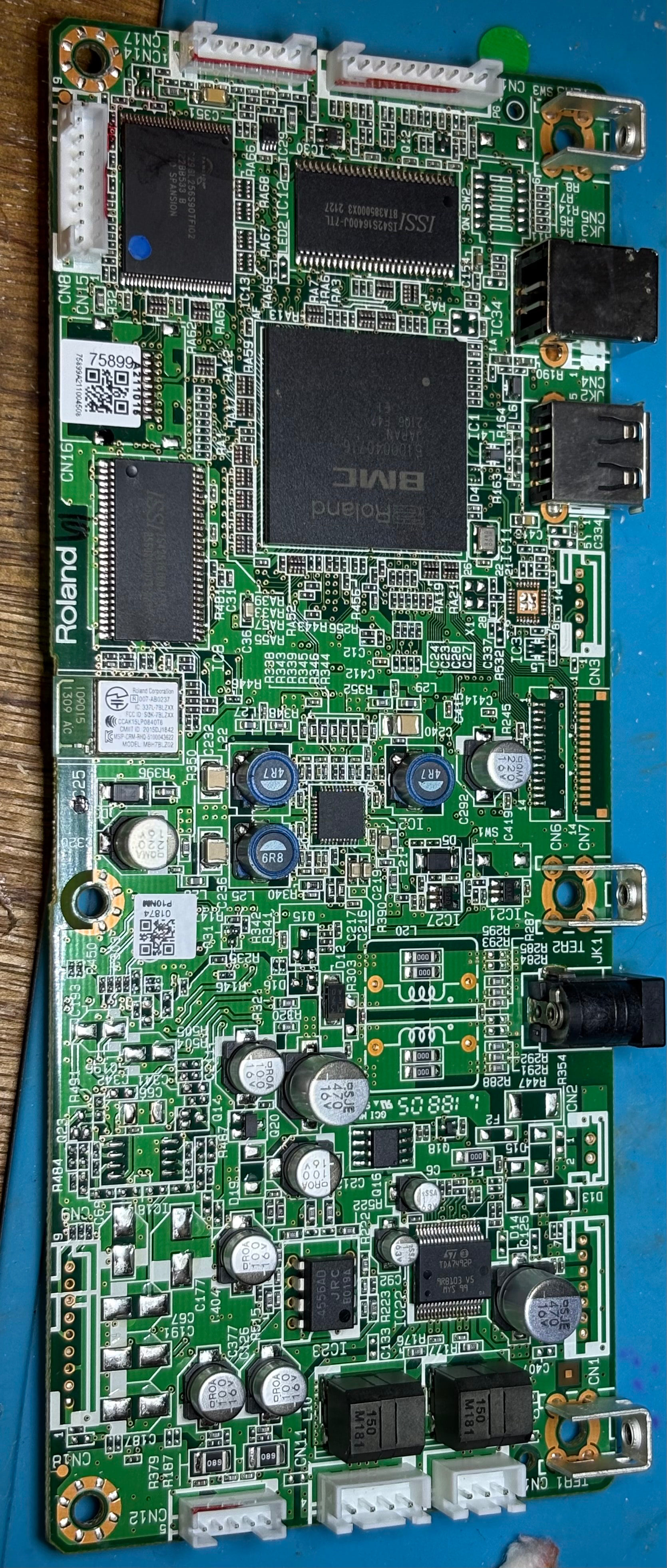
Hi. I have the same issue, but in my case, all the supply rails was fine. I check smd componentes searching for shorted caps or open fuse/resistor near the BMC Mcu and I find weird readings in some SMD caps and link resistors (tinny black smd resistors in the back side of the MCu). The good thing is after I check all this parts, THE FP-10 POWER PERFECLTY!!!. So I push a little this side of the main boad and the unit back to the bad symptom. I saw with a magnifier the back side of the main board and most of the SMD components in the MCu area, have a strange colour in their solder joints (looks a little blackened), so I reflux all this components and made a reflow to the BMC MCu. Not shure if the MCu reflow or refluxing the smd resistos/caps solved my problem, but obviously the failure was a bad solder joint. Hope this can help someone who have the same problems…
 .
.