Hi, I’ve been trying to fix this one for a while, maybe someone here will have some ideas. When I turn on the unit the LM311 chip overheats and fails. This a common issue google tells me, but replacing the LM311 didn’t help in my case.
Things I’ve tried:
- replacing IC8 (LM311)
- replacing IC7 (TL082)
- replacing the CPU (M5L8048)
- replacing C6 and C5 electro caps
- checking all caps for shorts
- replaced cable to the unit
- same thing happens on both a MKS30 and JX3p
- I tried not plugging in certain pins on the LM311 and here’s what happens:
pin 7 (output), heats up
pin 4 (-15V), does not heat up
pin 8 (+15V), heats up
pin 5, 6 (balance), heats up
pins 2, 3 (inputs), heats up
pin 1 (gnd), does not heat up, gnd = -12.4V
Any tips?!!
Thanks!
First of all: if the 311 is making troubles, then the first thing to do is to remove the CPU. If the 311 is dead it will send a voltage somewhere in the Range from -15 to +15 to the CPU which is most likely out of the allowed range of the CPU which is only 0V to +5V. It is a construction fault that there is no protecting circuit between pin7 of the 311 and the CPU (R10 does protect a little bit, but not really).
The next step is: remove all ICs and then check the supply voltages.
Check +5V at R10 and +/-15 at the solderpins coming from the 6pin DIN-socket.
place IC sockets for all ICs (use the industrial socket type with round holes)
Insert one IC after the other and each time after inserting an IC check all supply voltages. The second last IC should be the LM311, the last one the CPU.
Did you get an original Roland CPU? To my knowledge the CPU is not(!) clonable.
1 Like
Thanks! I’d like to try this but unfortunatley I don’t think I socketed the CPU when I took it out, so it would be difficult to remove it. Hopefully I didn’t damage it. The other 2 ICs have sockets though.
I got the CPU off ebay, i guess it’s a clone, title was “ROLAND PG-200 MASK ROM CPU M5L8048-067P VINTAGE SYNTH PROGRAMMER JX3P PG200”
Maybe just lift the pin on the CPU (TO pin 1) and look at the LM311 output?
LM311 is a comparator with open-collector output (emitter is pin 1 and collector pin 7 )
It should either be 0V or +5V.
It is strange that pin 1 (GND) is at -12.4V. Is that the pin 1 itself or the circuit ground voltage?
If circuit ground is at -12.4V that might overstress the LM311, causing it to heat up and fail (latch up state).
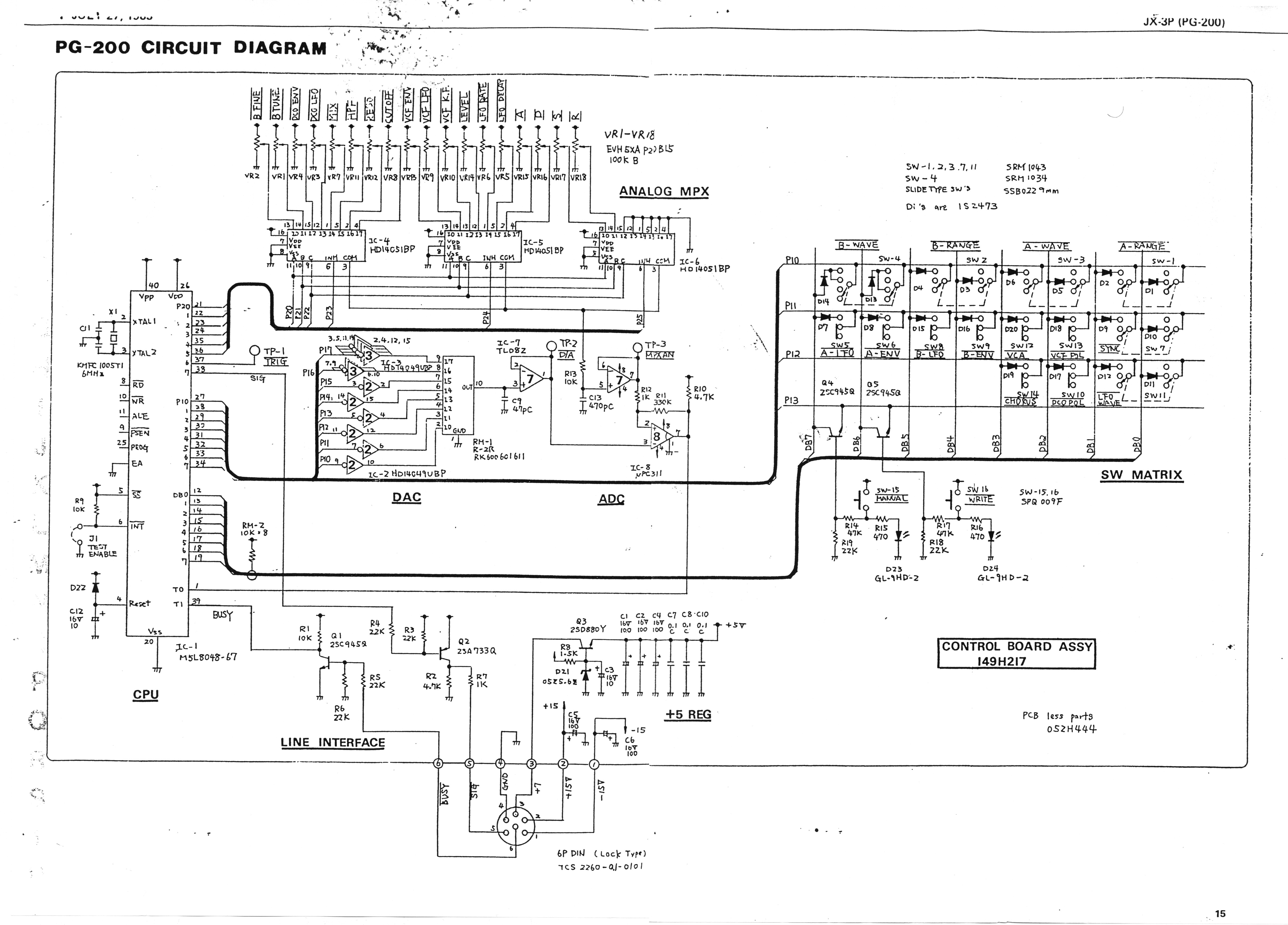
The DAC is a R-2R ladder (using successive approximation) to pin 3 of IC7. IC7 pin 1 should either show a ramp or step-wise waveform. IC7 pin 7 output is compared with IC7 pin 1 to perform a ADC function with LM311. The 18 pots (VR1 to VR18) are sampled one at a time with the ADC. LM311 pin 7 output is either OFF (open collector pullup to +5V) or ON (transistor on) pin 7 is GND + 0.2V.
The DAC IC7 pin 1 should only range from 0V to +5V DC since it originates from the CPU. Same goes for the VR1 to VR18 - there should only be 0 to +5V DC on the output of IC7 pin 7.
Maybe the LM311 is sensitive to latch-up which causes overheating?
I would have included two small (33 ohm) series resistors on pins 2 and 3 of the LM311 as well.
In a battery backup circuit from my job, the op-amp was latching up. Adding input series resistors solved the problem.
1 Like
Thanks, I’m going to try these tips.
Ok, I had a chance to try some of these things out tonight.
Fanwader:
- luckily I did socket the CPU, so was able to remove all ICs
- checked R10, it’s at 5V
- have + and - 15V at both DIN inputs
- check supply voltages on sockets with no ICs in, all good, IC7 and IC8 both of +/- 15V and CPU has 5V at pins 26 and 40… R10 at 5V… IC8 pin 7 is at 5V
- put in IC7 (tl082), same readings everywhere, R10 still at 5V
- put in a brand new LM311 IC8, CPU not in, except R10 is now at 5V on one side and -13V on the IC8 side
- LM311 still starts to heat up even with no CPU in
mjkirk12:
- I was able to remove the whole CPU
- with no CPU in, pin 7 of IC8 is -13V
- with no IC7 or IC8 in the sockets, pin 7 is 5V
- not sure why I wrote that the ground is -12.4 … it is 0V now … maybe that’s the voltage of the pin when I lifted it out
So, does that give you guys any clues? Again, no CPU in, and pin 7 of a brand new IC8 is at -13V.
Many thanks for the help!
i have the same problem! reading on diffrent websites about the IC8 replacement…
- did you find out whats going wrong?
- could you fix it meanwhile?
@adcbicycle thanks for your reply
No luck, I gave up and sold the non functioning pg200