My VCS3 developed an issue recently and we (my techie son) and I can’t seem to get to the bottom of it.
The trouble is that the outgoing signal is massively amplified - well beyond what it should be. For example, and incoming signal measured at 1.8 Vpp or so, passes through the filter, but is spat out the other side at a whopping 14.4 Vpp!
Oddly enough, as far as we can tell, the filter seems to be operating normally in every other way. And in fact, the filter’s own self-oscillation comes through the output at the expected 1.8 Vpp. It’s only the incoming signal that is massively amplified.
We’ve checked all the obvious (and some not so obvious), such as:
-PR6 set to produce 261Hz with Response (resonance) full and Frequency (cutoff) at half
-the diodes themselves (in fact, they’ve been replaced)
-the caps (also replaced the electrolytics).
-trim pots, the panel pots (replaced the former as a precaution).
-we searched for broken or bridged traces
-checked continuity throught the circuit
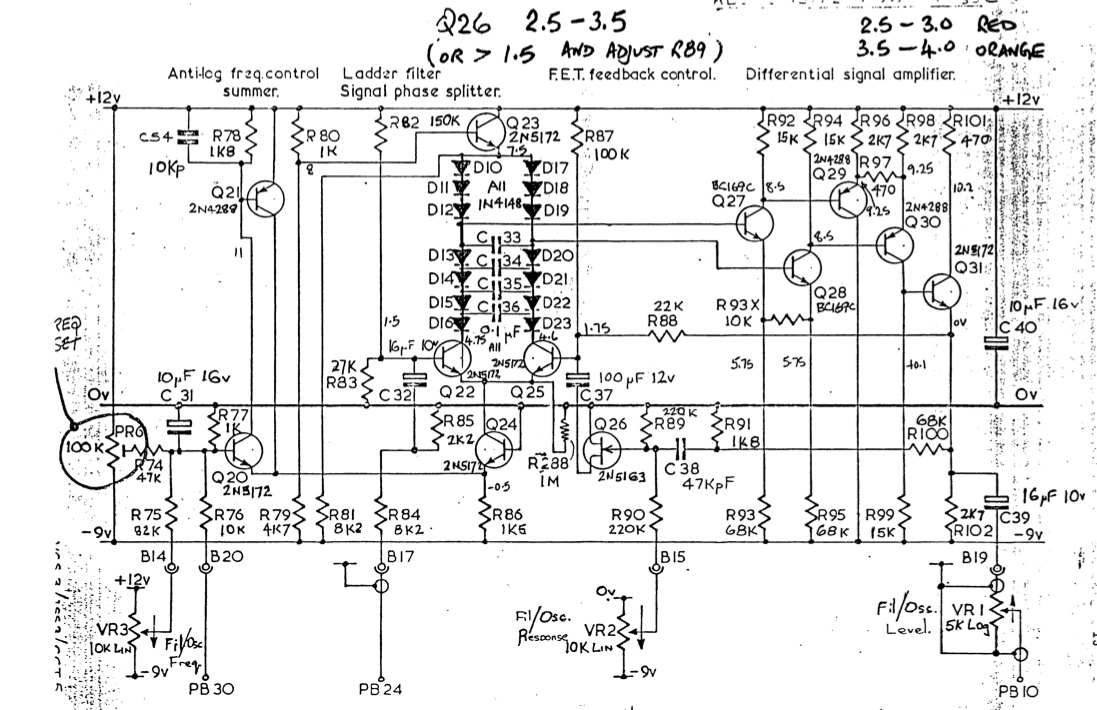
-Q26 (2N5163) has been replaced twice. Each attempt used JFETs selected with pinch off voltages within the 2.5-3.5 V range specified for that transistor.
-R84 and R85 have been replaced. The voltage after this divider is 300 mVpp, assuming an input of 1.56 Vpp (measured before R84).
-R93X, Q29, and Q30 have also been replaced.
-All of the voltages on the test points on the schematic match up fairly well with what we’re seeing.
And yet… The base of Q31 shows 14.8 Vpp.
Any help or suggestion would be most welcome. We are absolutely flummoxed, and I desperately want to get my VCS3 back into action. A screen grab of the filter schematic: