It powers up and I can hear very faint sounds coming from it when I plug into my DAW, with the volume up- everything still works, just no volume. I have a feeling I plugged the wrong power source into it at some point. When I took it apart, there are some black marks around DC in jack. Perhaps the power amp is fried? Suggestions? Thanks so much.
The circuit board reads 12 volts at the DC terminals. Any advice on what else I should be checking with my multimeter and how? Is there an online resource that goes over troubleshooting these types of synths? Advice is greatly appreciated- thanks!
When you say you hear faint sounds are they the type of sounds the synth should be making? Can you play the keyboard, adjust filter, etc? If so that’s a good sign, plugging in the wrong power adapter can really damage electronic devices but if you’ve got some sound then it may be an easy fix.
An oscilloscope would definitely help but you may be able to deduce what has failed without one. If the synth sounds relatively normal but just quiet you’re likely looking at a problem in the output circuitry. Does the headphone jack work? The power amp is only used to drive the headphone jack and internal speaker, the line out receives its signal from before the power amp… however the power amp failing could drag that signal down.
Anyways, first thing to check is the power regulator, IC7, at the power input. You should read 9V between pins 1 and 2. Let me know if you have any questions and be careful with your probes when checking the power regulator, you don’t want to short the pins to one another.
Travis, thanks for your reply. I checked the voltage at the !C7 power regulator and it looks good: 12volts going in and 9 volts coming out. The only sounds I hear are when I plug into the headphone jack and run it through an amp turned up to 11 and only then do I hear very faint sounds that respond to the keys being played and adjusting the filters, etc. This doesn’t happen when I plug into the line out jack. Should I try checking the power amp? Any idea how I do that? Thanks for your advice
Since you suspect you over powered the unit the safe course of action would be to unplug the keyboard, open it up and do a detailed visual inspection, looking for any signs of blown or damaged components, or funny smells.
What you describe sounds like a failed capacitor in the amplifier section, whether that was from time expiry or over voltage of the component is unknown until the faulty part can be identified.
Electrolytic caps leak electrolytic fluid before they time expire, and almost always expand or pop when they fail. Tantalum caps are hated bastards because they can fail by showing physical burning, but many times they fail internally without showing any exterior signs.
Start with that, and once you rule out the caps or other components then look at the power amp.
cheers.
Thanks for your advice, midnightvisions. I followed your suggestions and checked out the capacitors in the amplifier section. I ordered a capacitor tester and a multi-pack of electrolytic capacitors and replaced about 8 of them, as their readings were off. When I put the CS-01 back together there are some improvements, but the problem still remains. When I turn the volume up to 10, I can hear faint sounds coming out of the internal speaker, which it didn’t do before The synth is doing exactly what it should, just little to no volume. I My next task is to replace the internal IC amplifier. I ordered an LA4137 amp (the stock amp is LA4138) and the seller says they are equivalent. It looks tricky to remove, as there are about 18 contact points to the circuit board. Any further advice is greatly appreciated as I am really inexperienced. Thanks
We’ve all been inexperienced at some point. My advice is to not overheat the pads when desoldering because if you lift a pad it just gets harder. Use a good brand desoldering braid if you have it, and add a bit of flux to the board if you have it too.
Another crude method of removing IC chips if your having trouble is to cut the pins to remove the chip, then use forceps to pull out the pins in the circuit board one by one, while applying gentle heat to the solder. Its awkward but is possible. Its experience that allows you to get better at which method to use (and money and time and equipment ![]() )
)
I can’t find a schematic for that Sanyo amp chip so can’t tell you if its compatible or not. Both chips seem to be listed the same so at this point take a change and see what happens.
Good luck
I removed the old IC amplifier and soldered in a new one. Thanks for the advice re: desoldering braid and flux- it really helped! The results of the new amp were disappointing though. There was a minor increase in volume, but it is still unusable. My next step will be to go back and check the new capacitors that I put in, as they could have been compromised because of the old IC amplifier, but I really have no idea. Any suggestions would be greatly appreciated. Thanks!
if you have a small spare speaker lying around I’m going to suggest this.
solder wires up to the speaker, negative to ground and positive place on the output of the op amps - play a note on the keyboard, and follow the signal generation sound until it stops at a dead op amp.
There is a signal generation chip - place the positive speaker wire on that output pin, follow from the output to the next op amp chip and place on that IC’s input pin, then the output pin and follow the schematic untill you reach the IC that has no sound. That’s the dead IC.
Don’t touch the speaker wire to any other pins but the audio signal path pins.
The sound won’t be very loud, and don’t hold the speaker wire there for too long, just a few seconds to confirm there is sound there and the IC is working.
I tried your solution, midnightvisions, but I was unable to race the signal to a bad IC. Firstly, the output from the signal generation chip (3 pins) was a basic sine wave that didn’t come as a result of a key being pressed- it was ongoing. I traced the signal to one of the slider potentiometers and then it stopped. I really don’t want to start poking around touching probes to every pin for fear of damage. I am going to check the new capacitors I put in the amplifier section and see if the old IC amp caused them to fail. As always, suggestions are appreciated! Thanks for sticking with me on this one.
Speakers are low impedance loads so if used to probe the wrong spot (for too long at least) that could damage an unbuffered IC.
It’s possible a transistor has failed too. While the synth is powered up you should read about 0.6 V between the base and emitter terminals on any active transistor (emitter has the arrow, base is the middle on schematics, check data sheets for their pin-out). Some immediate suspects to me are TR7 and TR15. Even TR14, potentially; your low volume problem could have something to do with the VCA not getting it’s desired control signal.
Ideally you would check inputs and outputs of each IC with an oscilloscope until you find the problem begin then start analyzing which component around there might have failed or if a trace is discontinuous. It’s possible the fault could be in the filter section too but the VCA seems more likely for the symptoms.
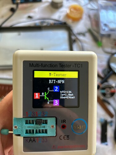
I checked the voltages of the transistors and found some anomalies. Most were in the range of 0.46v to 0.73v. TR5: 0.12v, TR13: 0.17, TR11: 6.68v, TR 9 fluctuated between 0.19v and 1.86v. Some were reading positive voltages and some were negative voltages. I pulled out TR11 and measured it on my meter- see the attached photo.
The Vbe (voltage between base and emitter terminals) of 596 mV (~0.6 V) from the out of circuit measurement is right in line with a healthy silicon transistor. It may have been that in circuit you measured the base to collector or collector to emitter voltage which is why you got such a high reading. The pinouts for some of them may be different from others depending on the type of transistor.
Can you tell if the envelope on the synth functions? Does the synth drone or are you able to play keys and adjust the length of the envelope stages? If the envelope seems to be shaping the sound how an ADSR should then I wouldn’t worry about TR9, TR11, or TR13 anyways since those handle the envelope generating. It is normal to get readings below 0.6 V depending on the transistor’s function in the circuit, I could see that being normal for those.
TR5 raises some questions, that one should certainly read around 0.6 Vbe, especially since the base is diode referenced to -9 V. That may deserve an out of circuit measurement. It could be that your synth has a weak oscillator output from that part of the circuit giving you a quiet volume over all. D40 could be bad too if TR5 isn’t, it’s function is to hold TR5 at 0.6 V so one of them may have failed.
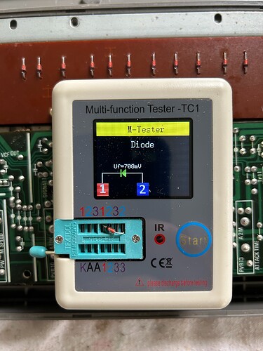
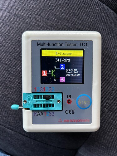
I measured TR5 again and it was 1.9v, which is quite a bit more that yesterdays 0.12v. When removed and measured, TR5 looks pretty much the same as the other transistors. I attached the image of the D40 so you can hopefully tell me if it looks suspicious.
Is there any chance of getting this to someone that has an oscilloscope? I’d really like to see what is at TP1, TP3, and TP5.
It sounds like the power supply section is okay, but it’s almost impossible to know if your problem is in the filter or envelope.
I am now looking for someone in my area to have a look at it, which isn’t as easy as I thought. Thanks for all of your suggestions, guys. It has been great to get all of your advice and recommendations. I’ve learned a lot along the way as well. Cheers!


