That was my assumption, but now I’m thinking there was nothing wrong with it. After replacing it, the sound was great for about 30 minutes. Then I went to use the volume slider and BAM, super low volume and distortion. This is on the “good” DX7. This sparked a memory that when I first got this board, it did that exact same thing, but came back the next day and was fine for several weeks. Replacing IC40 somehow kick started it again, but now it’s back. I swapped the entire jack board and the left panel with the sliders with boards from my other DX7 and there was no change.
For now I’ve stopped randomly replacing stuff before I make it worse and have been carefully checking voltages on the main board. For some reason, the ram chips only have like 2.5 or 2.7v when the board is powered. I know it’s not the DC power board because I have several and they all give the same response (and voltage check shows the colored wires into the main board all have the right voltage). I suspect there’s something early on the board (maybe D4 or the tantalum capacitor?) that’s the cause but I am not sure yet.
Okay, so the ‘good’ DX7 isn’t really good?
My first thought with something as intermittent like that would be a bad connection somewhere. I just wouldn’t expect something to work part-time with bad components. I’d examine the solder on all connector pins.
2.5-2.7v sounds like battery voltage. (Assuming you’re measuring across pins 12 & 24) It’s okay for maintaining the contents of memory, but I would expect the operational voltage to be around +5v when the DX7 is powered on. Does the DX7 call up sounds okay when the voltage is that low? It’s an interesting find, but I’d check the voltages around the D/A converter and through the analog side to see if they’re low, too. (Going back to a bad connection - you might be losing voltage to the board across a bad solder joint.)
I haven’t seen dead tantalum caps personally, but I’m told they are a dead short when blown. And the bad electrolytic caps I’ve pulled out act more like a resistor.
Yes, you can tell the sounds are there, they change and the screen shows them correctly. It’s just that the volume is REALLY low, and there’s an added distortion to every sound. Meaning you can tell the difference between say, a flute and some other sound, but there’s distortion over it. At one point it was loud before I replaced IC40, then it was fine for a while and now it’s just super quiet.
Okay, I’m getting a bit more clearer readings today. For some reason, the ram voltage is good today (and has been the last few days), but I’m pretty sure I’m losing the 15v somewhere along the line. According to the schematics, it should be 15 on IC 40 pin 7 and IC 52 pin 14, and IC 45 pin 7. It’s only 7.5 on all of those, so something is cutting it in half. The schematic isn’t all that clear on voltages around every component so it’s hard for me to trace back to where it’s happening. I’m googling to see if I can find a post somewhere listing more voltage points so I can measure them. Also, I’m grounding on the case near the ground wire for the main board and/or a screw in the center of the board and I get the same readings.
Measuring IC 41 just now, I get 15v on Pin 8, I get 132 on Pin 9 which I find really strange. Pin 10 is 15v. Somehow as I was testing IC 41, the volume jumped back up to full, but it’s still distorted. And I get crazy readings on pins 5 & 6, like 140v, which is crazy. I’m thinking either it’s something feeding IC 41 or it’s IC 41 itself maybe.
I’ll keep carefully testing. I think the weird 100+ may just be my multimeter not understanding whatever that pin is putting out because yeah, you’d think it would be smoking at that point. One crazy thing is, as I test (carefully, trying not to short anything), the volume has gone loud and held for a few days, then quiet again, now it’s loud again and holding. Still distorted heavily, but loud and fully functional except for the distortion.
Thanks for the info, I’ll keep at it.
I would love to jump into this discussion to help - but only if Profile - ProfTrudo - Syntaur Forums doesn’t get upset - there’s a lot of bad and mis-leading queues in previous posts …
Just a little hint here:
Any OpAmp needs to run in a balanced operational mode (unless it is a comparator) … that is what the 7.5V line is all about. Since the DX7 is running asymmetrical power (ie +15V only) any OpAmp needs to be BIASed into its balanced operational mode. Think of it that way - if the In- point is set to 0V (GND) how would the In+ signal go negative half-wave when supplying a full wave sine signal? That said - any OpAmp that is running as any sort of amplifier needs to have pins In+, In- and Out to be set at this equilibrium point - hence, in the DX7 any OpAmp running on +15VDC supply needs to have In+, In- and Out sitting at approx BIAS point which is 7.5V. If an OpAmp has any of these three pins at any other level, being it way higher or way lower, you can almost guarantee the OpAmp is bad. That is also the reason you see a lot of coupling and -de-coupling capacitors at any OpAmp input and/out output … because the finite signal is measured against GND (0VDC).
Also - when measuring DC voltages, and that will be 95% of all cases, always use a tested and verified GND point … not ANY other points for reference (there are of course exceptions - but they are rare).
Hope that helps a little …
More than happy to welcome someone else into this discussion. I’d prefer to follow along if you have some ideas.
And if I’ve given any bad advice, I’d like to remove it so that it doesn’t steer anyone else in the wrong direction. With two DX7’s in the mix, I’m afraid it’s confusing enough.
Frankly, I’m more troubled by the idea that you’d think I’d be upset about about your jumping into the conversation than I’d be about someone jumping into the conversation.
I welcome the help. On the main board, is there an official ground point? I’ve been grounding to the casing right above all the wiring harness connectors, near where the ground wire connects the bottom case with the top case. So far it seems to work okay as a grounding point.
Also, to make sure it’s clear, I have 2 DX7s. Both seem to function completely except one makes no sound, the other makes this distorted sound.
I’ve been measuring the one with no sound today and pressing keys to see if my scope bounces. Tracing from the right side of the board, I can see signal changing when I press keys on IC 11, 13 and 60 so far. But farther on there’s mostly nothing. The ram chips have 5v on pins 1 and 13 but NOT 12 and 24 for some reason. The opticoupler has 5v on 1, 2, 4 and 6. IC 10 has -15 on pin 4, +15 on pin 5 and like .5 on all the other pins. Same on IC 9.
OK - here it goes.
First I want to propose a complete RESET. Let’s work ONLY on the unit that has NO SOUND - forget the other one for the time being and forget everything being done before - clean start.
Second - forget the oscilloscope for the time being as well.
As an aside - your oscilloscope won’t be much good for the digital side anyway. To look at the signals on the digital side you need a logic analyzer - I don’t think you want to spend a few k$'s on that. A standard simple oscilloscope can see logic dataflows as bands of highs and lows or maybe even distinguish hihg/low transitions but cannot trigger on them either. To do that you need to setup your scope for external triggering and find the respective trigger source on the bard itself. Also logic highs and lows on TTL circuits such as the DX7 are not defined as 0V (low) and 5V (high) - in reality a LOW is anything below 0.5V and a HIGH is anything above 2.0V (usually about 4.5 or thereabouts). If you read a logic stream with a multimeter you will read an average of around 2.5V … can be somewhat higher or lower depending on the amount of highs vs lows in the stream.
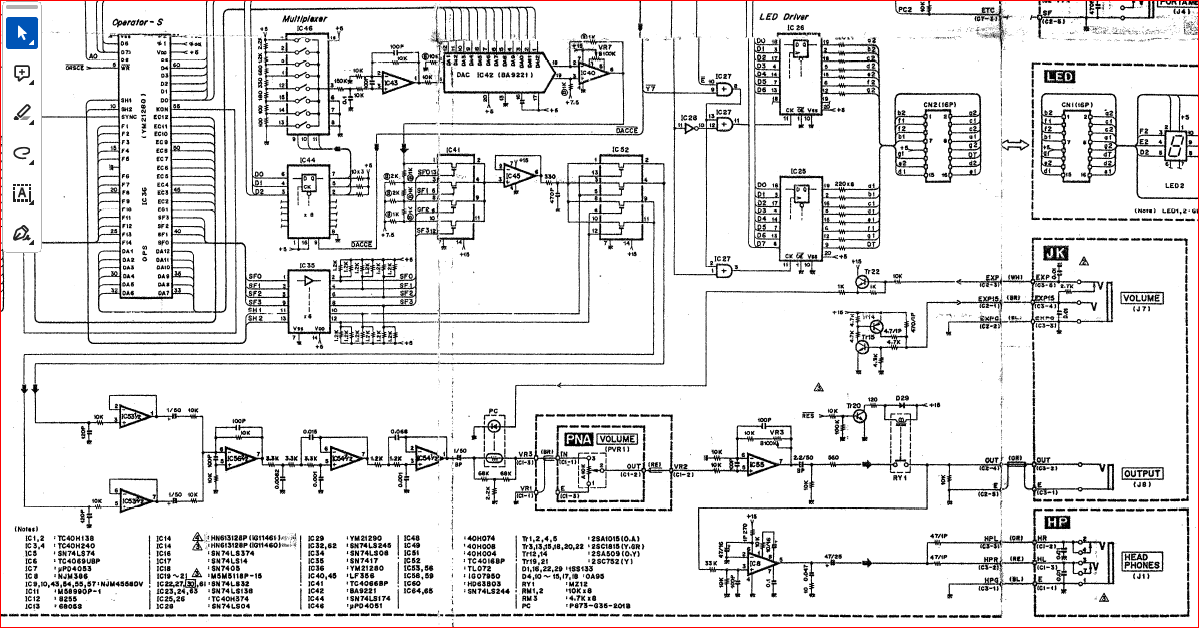
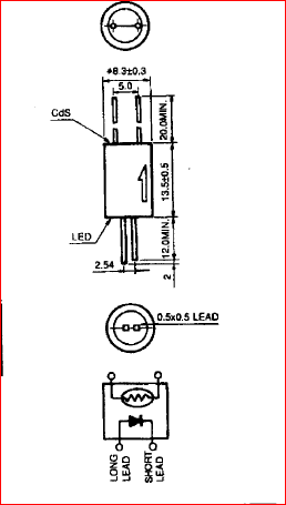
For the moment let’s just concentrate on the analogue section after the DAC IC42 (see pic)
I hope you have got headphones or even better a little cheap amp you can attach to the output jack.
What kind of volt meter are you using BTW?
The first thing we need to do is verify all the OpAmps starting at IC40 … IC45 … IC53 … IC56 , IC54 … IC55 and measure the DC levels on each the “IN+”, “IN-” and “OUT”.
For IC40 and IC 45 that is pins 2. 3 and 6 for all the others being dual OpAmps these are pins 3, 2 and 1 AND pins 5, 6 and 7.
Any value that is outside of around 7.5V DC we have to investigate further.
Just to follow up, I haven’t abandoned this, I’ve had some things come up and haven’t been able to get back to it. Hopefully this week I’ll revisit this. I absolutely appreciate your help, I just haven’t been able to get back into it yet. I’ll post back when I have a chance to do all the tests you suggest.
Thanks!
Okay, I just measured all the pins, all the Opamps and the opticoupler. Here’s the numbers:
IC 40
1: 14.3
2: 5.3
3: 5.3
4: .1
8: .1
7: 14.8
6: 7.2
5: 14.3
IC 45
1: .1
2: 7.2
3: 7.5
4: .1
8: .1
7: 14.8
6: 7.2
5: .1
IC53
1: .1
2: .1
3: .1
4: .1
8: 14.8
7: 7.2
6: 7.2
5: 7.2
IC56
1: .1
2: .1
3: .1
4: -15.3
8: 14.8
7: 9.2
6: 7.2
5: 7.2
IC54
1: 9.2
2: 9.2
3: 9.2
4: -15.3
8: 14.8
7: 9.2
6: 9.2
5: 9.2
IC55
1: 14.3
2: 1.6
3: 1.6
4: -15.3
8: 14.8
7: .1
6: .1
5: .1
IC10
1: -1.1
2: .1
3: .1
4: -15.3
8: 14.8
7: .1
6: .1
5: .1
IC9
1: .3
2: .1
3: .1
4: -15.3
8: .4
7: .4
6: .4
5: .4
Opticoupler
1: .1
2: .1
3: .1
4 (6?): 4.8
5: .1
6 (4?): 4.8
Edit: fixed the order
WOW !!!
To start with - you got your chip pin numbering all wrong! They go like that
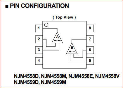
From the dot count down and then on the other side back up.
That had me confused looking at your pins. I hope you were consistent then I can always assume
1=1
2=2
3=3
4=4
5=8
6=7
7=6
8=5
Then the readings do make more sense.
At this stage everything until IC56 looks good - IC 56 (pin 5,6 and 7) and IC54(pins 3,2,and 1, pins 5,6 and 7) is no good.
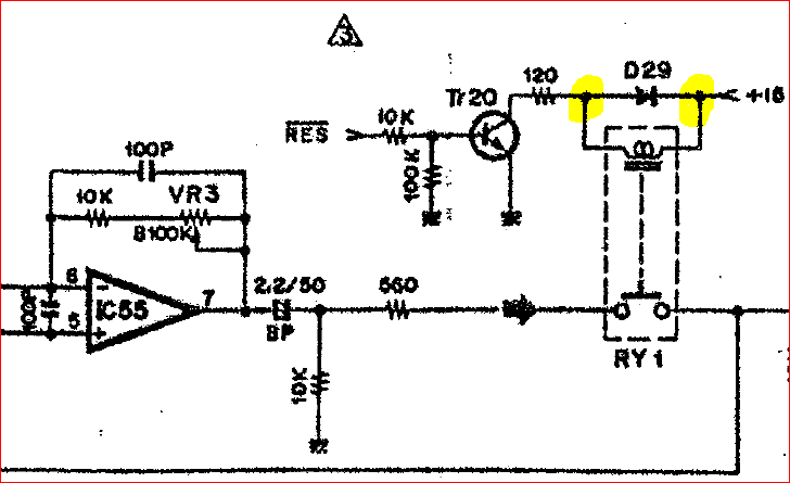
Since IC56 and IC54 are attached to ±15V supply and decoupled on each side (see yellow below) then the afore mentioned pins should be around the 0V mark and they are not…
Can you remove the two 1/50 capacitors after IC53 and measure IC56and IC54 again.
Additionally - can you give me the voltage readings on both sides of D29 please.
ah! Yes, that makes sense about the pin order. I did them all the same way, thinking it just went up one side and up the other. I’ll work on this a bit and get back to you.
Also, you asked me what my multimeter was. I have an Ideal 61-347. I also have a little DSO-152 digital Oscilloscope (works pretty well for measuring voltage too, so I’ve been using that mostly), and recently I modded a mono audio cable to 2 alligator clips so I could probe for audio signal. It works but so far on all my projects it’s not really helped much yet lol.
Okay, I had replaced 56 and noticed that there’s a connection to a component next to it that was supposed to be connected but wasn’t showing continuity. I fixed that (I’d go into detail but I already put it back in the case). The new readings for IC56 are:
IC56
1: 7.2
2: 7.2
3: 7.2
4: -15.2
5: 0
6: 0
7: 0
8: 15
IC54 then is:
1: 0
2: 0
3: 0
4: -15.2
5: 0
6: 0
7: 0
8: 15
these are WAY off from what they were. And honestly, I’m not sure this board is stable this far over, so I may get different readings every time I turn it on. I’m going to let it sit for a bit while off and then retest it.
Hey, that is perfect … that is how it should be !!! IC56 pins 3,2 and 1 are not used … therefore floating hence the weird 7.2 … all others are spot on!!!
I have an issue with OptoCoupler - it only has 4 pins … you show readings on 6 pins ???
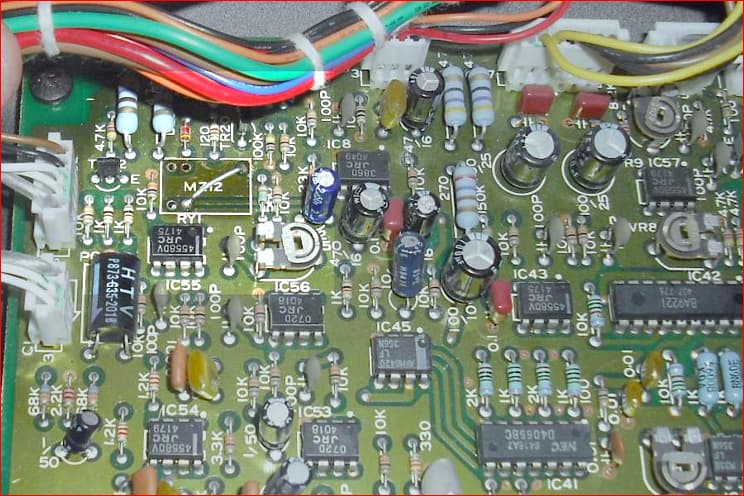
and looks like this:
I may have gotten confused as to what the optocoupler is. I was measuring chip PC900. Where on the board is the optocoupler?
Left in picture - reads “H T V” on it.
BTW the empty space with the diagonal wire bridge is the the Relay RY1 near the output removed and bridged
I had bridged the relay and then put it back in as that wasn’t the issue. I googled PC900 and it is indeed an optocoupler, so I guess this is a Photocoupler (based on a googled PDF info sheet for the P873-G35-201B). Measuring it based on the photo you posted, the top left pin has a gold ring around the solder hole. That pin is zero, the one to the right of it is 2v. The two pins on the other side are also both zero.
On a side note, I’m not sure if this helps work backwards, but pin 32 of IC36 is zero. On the other DX7 I have that’s putting out distorted sounds, that pin has voltage (I need to measure again how much, but it’s not close to zero as I recall). I’m wondering if something is blown much further back or if IC36 is bad (no way I can replace that one sadly).
That Opto looks good too - forward voltage according to datasheet is 2.1V … you measured 2.0 ← near enough.
Not to distort what we are pursuing right now; that pin 32 is part of the digital signal created when pushing a key to create a sound. Pins DA1 … DA12 then go to the 12-bit DAC IC42 (BA9221) to create the respective analogue signal. When no key is depressed I would assume all these pins to be 0 Vdc or very close to 0 Vdc representing a digital “0” giving an analogue out of 0 Vac … see below table:
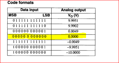
Depending on the bit combination data stream that creates the analogue sound.
NOTE:
It is important to recognise that in a digital system it is near impossible to ascertain signal levels with a DMM because a DMM will attempt to represent an RMS value of the readings … both DC and AC - ie the more "1"s as opposed to "0"s on the respective pin the higher the voltage reading on the DMM. You will need at least an oscilloscope with a speed to display at about 10x clock speed of the device you are looking at.