Just trying to get some sound out of a yamaha DX9 at the moment. Battery been replaced, working fine… nothing from heaphone or output jack…
I had a helpful person at syntaur suggest it could be the muting relay. When I look at the parts list, it is called a MZ-12 relay. I can’t find any real information about these online, the image I’ve taken here is the only image of one on the internet probably haha: Imgur: The magic of the Internet
If this relay is my problem, am I able to test it with a multimeter? Is there anyway that I could replace this relay, given they are out of production and no other replacements seem to exist online? I doubt I can, and this must be a long shot to say the least, but any information you can provide I would appreciate, before throwing the synth in the bin!
how would I test the relay mute control, or is that just part of the relay itself. It doesn’t work now unfortunately.
Where would you go from there Werner?
I have a multimeter, and i have a full set of capacitors arriving soonish for the DX9.
Is there anything I could try until then? Sam from syntaur also sent through the full service manual for the DX9, which was great as all the other versions online don’t have it.
If that does not work now … then the problem is NOT the relay … have to go further back in the circuit …
Don’t play with capacitors as of now … that may confuse the issue even further … first we need to find why there is no sound. Just running out changing caps may work but also may back-fire … bad new cap (not unusual) … made a little mistake changing caps … etc etc . … then you are hunting two ghosts!!!
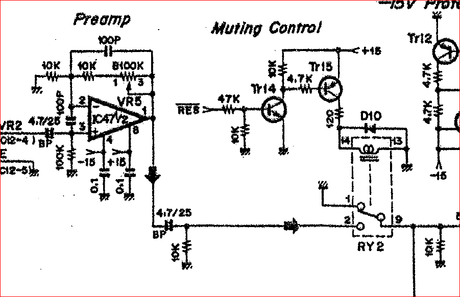
Since you have now the circuit diagram available … measure all IC pins from IC47 back to IC39, ignore 41 and 43 for now) and check all pins where pins 1,2,3,5,6,7 should read around +7.5VDC (or about 1/2 pin 8) and pin 8 about +15V and pin 4 about 0V (GND).
please excuse my ignorance, im very new to this and have been trying to find out online.
so just checking, if I am measuring the one in the photo… would that mean, that my red pin of my MM is and then i go around with it on the diode setting and check what you wrote in the last post?
Hmmmm … since you got the schematic I assumed you may be versed in electronics …
OK … here it goes.
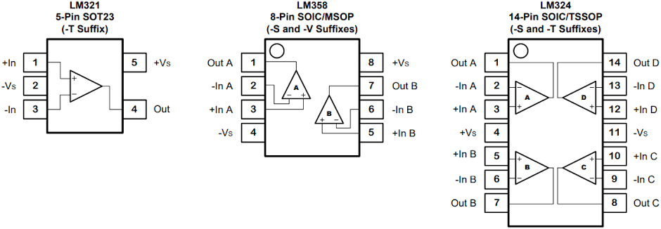
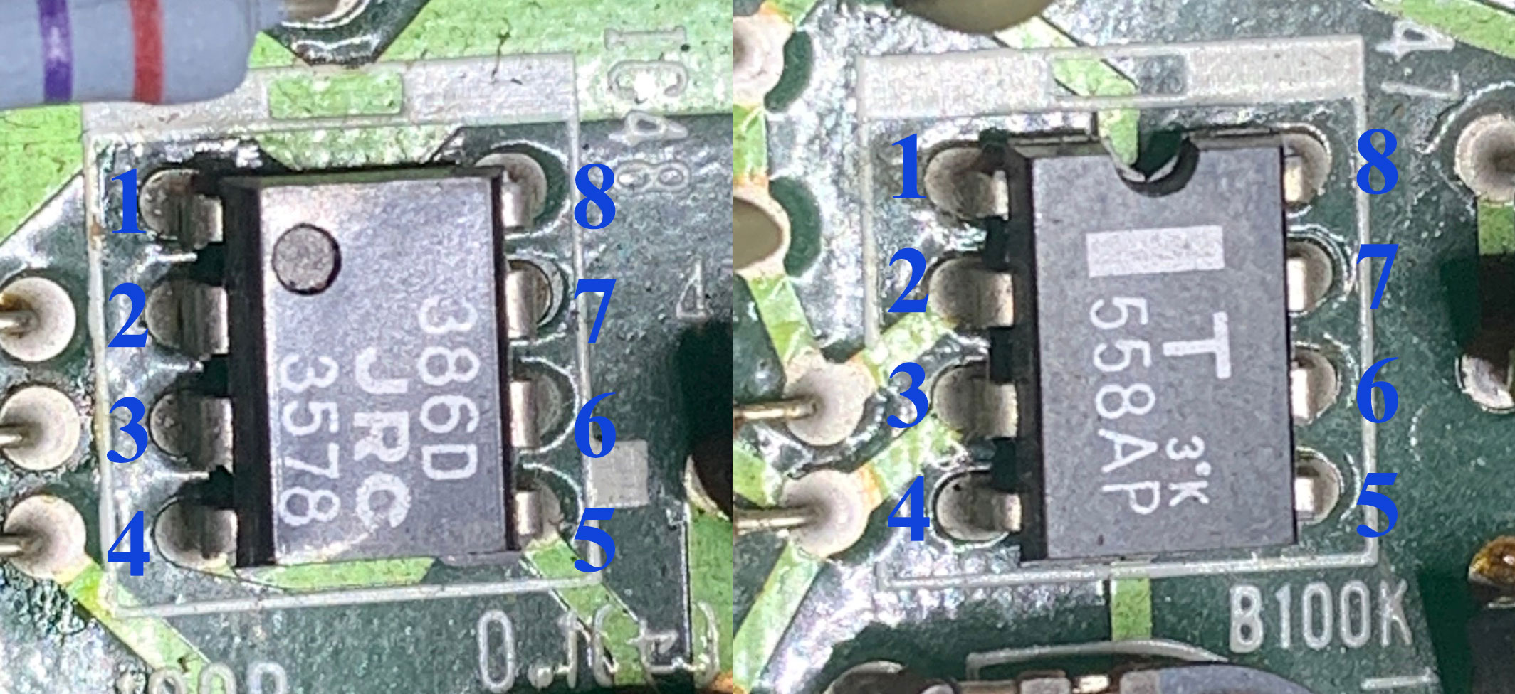
Attach MM black lead (GND) to some good ground point … then use the red lead (V) and put it onto each of the IC pins - pin 1 is where the dot is … ie like this picture middle chip
In your first post regarding pins you said “measure all IC pins from IC47 back to IC39, ignore 41 and 43 for now) and check all pins where pins 1,2,3,5,6,7 should read around +7.5VDC (or about 1/2 pin 8) and pin 8 about +15V and pin 4 about 0V (GND).”
But then in the second one that if I slip from pin 8 and touch pin 7 that it will kill the chip.
I’m sure im reading this wrong but just want to check, because I thought maybe in the top message you’re saying touch pin 7 but then in the second don’t touch it or it’ll kill the chip.
Also, should the battery be disconnected from the board?
do I have the pins labelled right on these diagrams?
What I was alluding to regarding pin8 and pin7:
IC pin 8 is +15V - should you accidentally slip with the meter probe and touch pin8 together with pin7 you will put +15V to the output of the second OpAmp in the IC (see above example if the LM358 IC) that’ll kill the second OpAmp, sometimes the entire IC - just a warning to be carefull.
Good lord. I’m not sure what i’m doing wrong here, but I’m very conscious of dragging you into my insanity with every minute question I ask. I will go into Jaycar tomorrow, see if they can set me on the right track, and once I can get something of a semblance of a normal readout, I will send through each reading.
Do you have discord Wernersaurus or something of the like so I can send through the schematic?
Just came back from Jaycar, brought the circuit board with me. The guys couldn’t have been more unhelpful. He couldn’t even help me ensure I was finding ground on the circuit board.
I was trying to get him to help me in finding out why the numbers on my multimeter were all over the place, and why the readings were going down in number as i used them. He said ‘may the force be with with you’.
On a lot of chips/pins i get no reading, and then on others the number just drops… I will upload a video later today
here is a video of a few readings or lack of readings.
I also got some others where the voltage just consistently decreased - the guy at jaycar said this would be leaky capacitors, but like you said I don’t wanna necessarily look for 2 ghosts and install them before I need to.
Is there anything about this that makes sense to you? Is there anything else I could try to trouble shoot.
thank you again for your help thusfar and patience.
I can chime in here as well, Aussie tech in Sydney. I’ve worked on a few of these, the 7 and 9. Not at all easy to work on these things especially for a beginner. You say the battery is ok ? Did you change the battery or you got it like this? If YOU changed the battery the patches need to be reloaded via sysex!! On the 9 unlike the 7 there’s no patch names to give you a clue that the patches are garbled and need reloading. A 7 or a 9 will make no sound with the memories empty or scrambled. On the 7 and should be on the 9 there’s a there is a function to make an “Init patch” which just gives you a sinewave. If you hear that then you just need the patches reloaded. You need a MIDI interface a program like MIDIOx, MIDI cable and some patches which you can find online. Then look up the manual how turn the memory protect off, enable sysex on the DX9 and send some patches from computer to the synth
Good to hear from you Ivan. I’ve reloaded the sys ex patches a few times from midi ox when I first received it, everything seems to have worked there but I wasn’t able to get a sound from the thing unfortunately. The previous owner had just recently replaced the battery that way, I’m getting good readout on battery through the battery check on the synth itself.
Ok I had to check that first. I had one that had the same symptom and it was due to the clock generator that runs the two FM chips. I agree with Werner’s comments in that the output opamps might be faulty. First thing though you need to be sure you have a correct ground point. Find the ROM chip or one of the two RAM chips they’re IC6,7 and using the same numbering scheme as you have in the pic the bottom left pin is 12 this connected to ground. Now using the continuity mode ie the beep function find other places on the board that make the meter beep you might be able to attach your ground lead on your meter. You might need some other tools if you don’t have them so at jaycar buy some side cutters and the needle nose pliers these are an absolute must.
hey Ivan,
just went to jaycar and took your advice to grab some needle nose plyers and sidecutters, and also an alligator clip to keep my other hand free to maybe record a few bits of video to send through some results.
I took your advice with the IC7 chip on PIN 12 to find some other ground sources…
The black solder point of the battery works as ground.
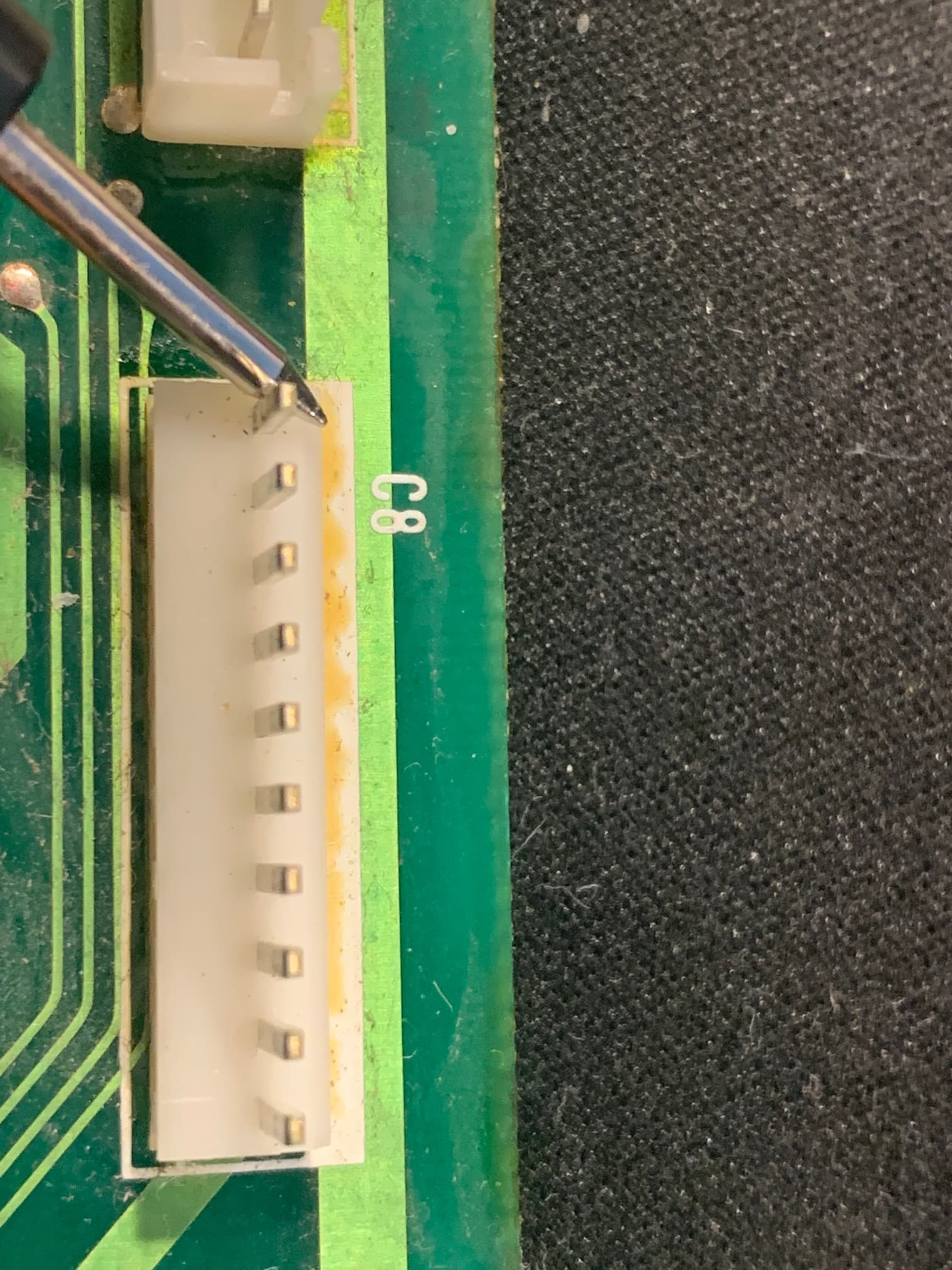
I also found the C8 pin would work as ground as it was beeping on the diode MM setting.