Okay excellent, that’s really step number 1! Now you can actually believe what your multimeter reads and it will make sense. On the op amps you had before you should now read -15v on pin 4 and +15v on pin 8. All the digital parts run on 5v which you can see on the corner pins of the digital chips ie on pin 24 on the RAM you will either see 5v with the power on or the backup battery voltage on the one that’s connected to the battery ( one is, the other isn’t). I would be looking at the opamp outputs ie pin 1 and pin 7 when you press keys hopefully you see a small voltage probably. But really you need a scope for work like this.
Gday Ivan,
I ordered a scope a few days ago, it should be coming in the mail already, and will let you know when I have it.
I know this is worth less than your time, and i apologize for the long video but I was just testing both my multimeters again and getting weird results, so just wanted to check. I guess my multimeter misbehaving is probably the first port of call, so just want to see which to use.
Sorry I had to have a good chuckle! Of course you’re gonna see nothing when there’s no power to the board ![]() All the measurements we are talking about you have to do with the board in the machine all the connections in place, powered up and running!! Do you know how to do this safely? Ie do you know where the dangerous voltages are and where not to put your fingers? Basically you stay away from the right hand side of the machine where the mains comes in which is to the right of the big lump of iron ie the transformer. As long as it’s plugged into the mains there’s 240v there even when it’s not powered on! Actually take a picture of that side of it and post it here. There’s actually a reason why you need to remove a part before it goes bang and starts smoking or catching on fire. There’s a RIFA in there !
All the measurements we are talking about you have to do with the board in the machine all the connections in place, powered up and running!! Do you know how to do this safely? Ie do you know where the dangerous voltages are and where not to put your fingers? Basically you stay away from the right hand side of the machine where the mains comes in which is to the right of the big lump of iron ie the transformer. As long as it’s plugged into the mains there’s 240v there even when it’s not powered on! Actually take a picture of that side of it and post it here. There’s actually a reason why you need to remove a part before it goes bang and starts smoking or catching on fire. There’s a RIFA in there !
Good lord. One of the most embarrassing things ive done in a while, kill me now.
I’ve been watching all these guys do it on youtube with disconnected parts, the chip often just sitting on some foam or something, so I thought definitely nothing is plugged in.
Major knob head, going to try now.
I’d recommend watching some synth, vintage computer repair videos etc Maybe I need to start my own channel, school the younger generation ![]()
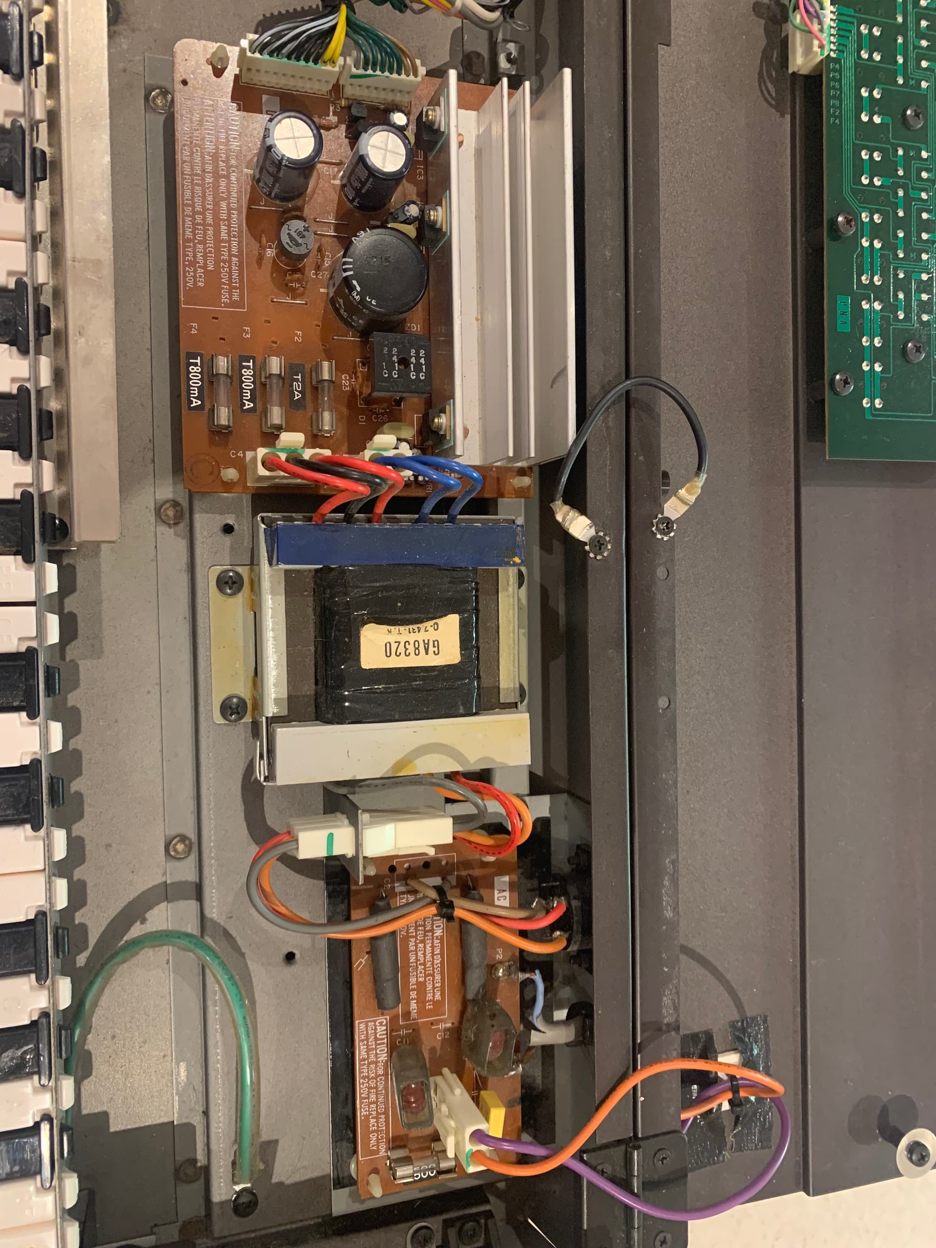
Ok so my concern has been eased, it looks like it’s had recent attention because the original RIFA capacitor has been removed and a new suitable replacement installed. The bright yellow block near the power inlet is the replacement. Machine is safe to work on. So basically stay away from that whole area when the power is on that’s where the ouchy is ![]()
thanks for your help Ivan, unfortunately I’m heading out for the night to my girlfriend’s soon.
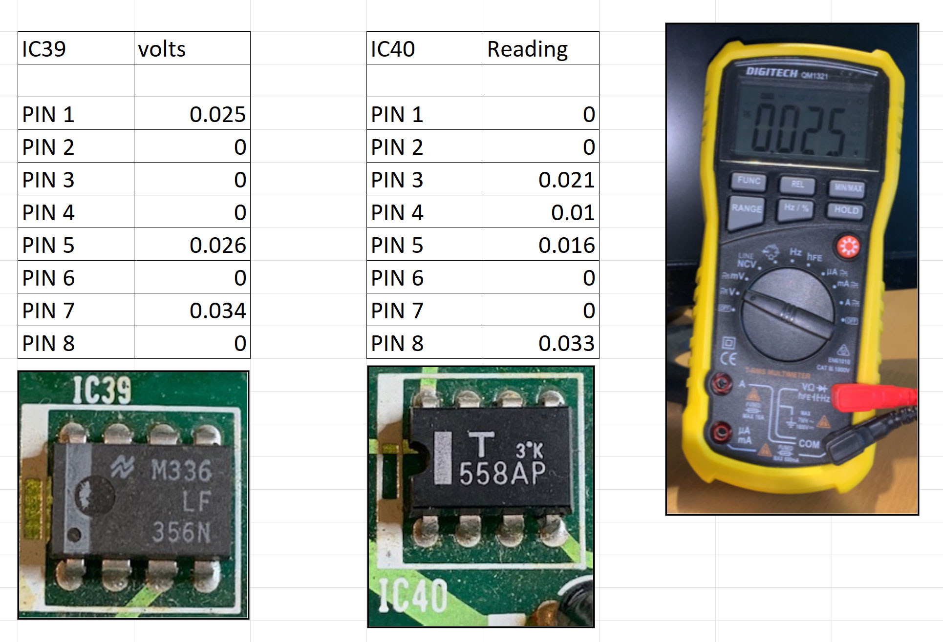
I just did a few very quick tests on Pin 4 of all the Op Amps.
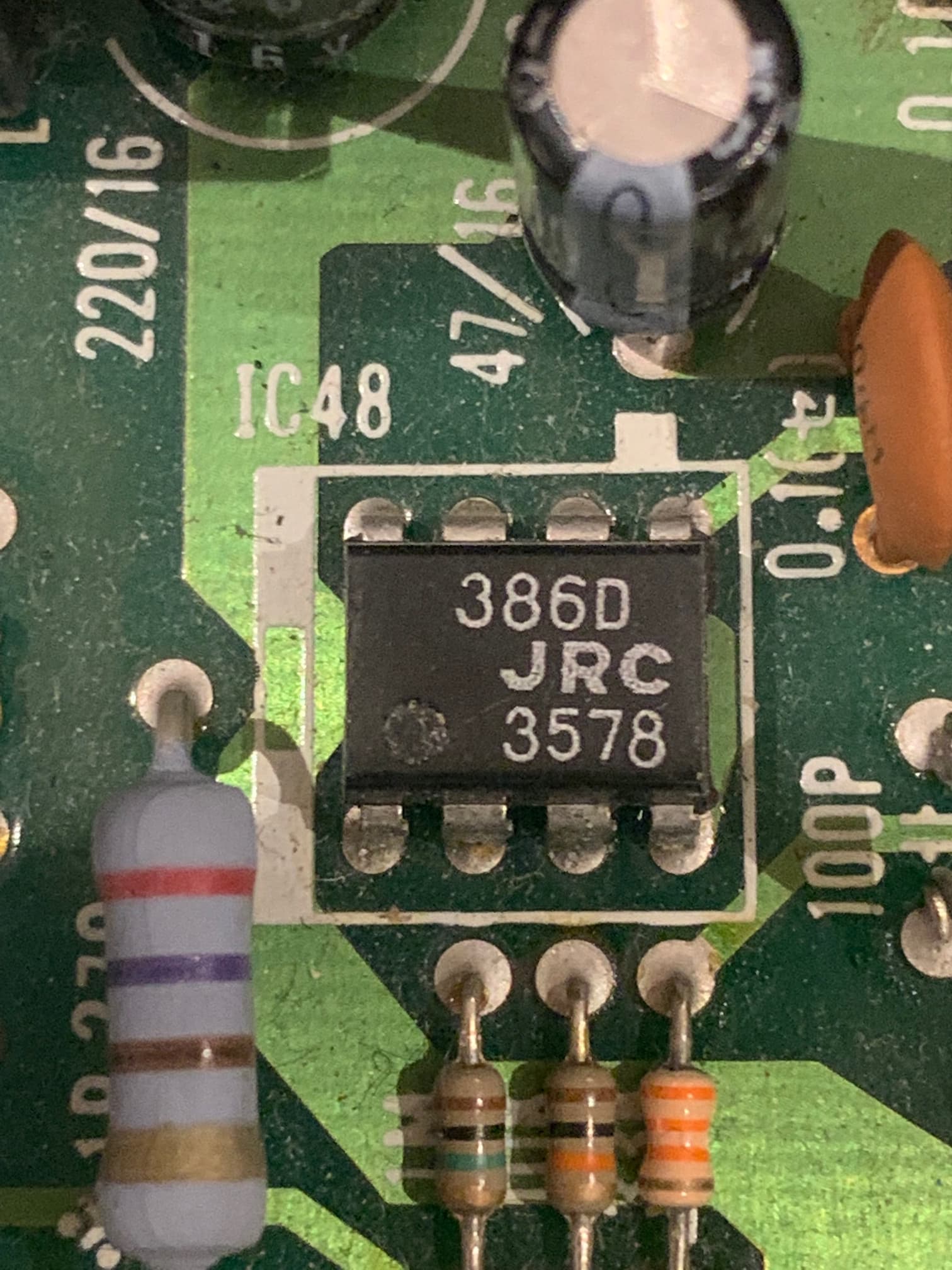
IC 48 seems to be the issue possible, as I don’t get a reading on Pin 4.
It looks like IC 48 might be the issue just from the super quick test I just did.
Some are also a bit under 15v, like around 13v or 14v.
No wonder everyone stopped replying on other threads. I was supposed to have the thing turned on. Good god ![]()
![]()
![]() .
.
are these things replaceable if it is this? I googled them a few days ago and struck out/couldnt find much of anything.
Having a look at schematic that’s the headphone preamp so that indeed only has +15v on pin 8 and pin 4 is connected to ground so zero is correct. I doubt that’s the problem if it was you’d hear sounds on the main ours but no headphones.

Ok I’m hoping your meter wasn’t on the setting in the picture. It needs to be on Volts which is the one with the V symbol on it, to the left. With the power on and your black lead of the meter on a ground point your red lead on the test pin. We need to see if power supply voltages are correct. IC40 pin 4 should read -15 or close to and 8 should read 15. Pin 7 should read 7.5 and pin 1 9.53. IC40 is actually used as a reference voltage for the digital to analogue converter (DAC) chip which is what was dead in my case.
The meter is now on the correct setting for measuring voltages. But if you did it correctly ie the black lead was on a correct ground point everything plugged in and the power on it then you got bupkis!! Ie sweet fark all. So first thing I want you to do is to unplug the machine from the wall then go back to the diode setting, no need to remove anything from the machine. In the picture you posted there’s 3 fuses on the power supply board which is left of the big lump of iron ie the transformer. Touch both ends of each fuse with your two leads of your multimeter in beep mode. Do they all beep?? I am hoping one doesn’t, those are the fuses for the +/-15v. You will have no sound without those voltages. If all 3 beep then you put the voltmeter back to V. Plug the machine in, turn it on. We gonna measure the voltages out of the power supply at where they exit. In the picture you see a whole bunch of black leads, shove your black probe in the connector itself on any of those and your red one in brown one you should see 15v. Then move the red one to the yellow it should say -15v
hey Ivan,
I’m probably checking the wrong things here all together. But I put it on beep diode setting and checked the 3 parts which have arrows on them.
I got a beep from the 2 long black parts which I put green dots on, but nothing from either side of the yellow parts pins which I put a red dot on. Like I say probably checking wrong part.
The guy when I picked it up said that he recently replaced the … safety cap or something, he was in a rush and didn’t explain much, but I know he was referring to that yellow one.

No no that’s the high voltage end don’t touch that, with the machine plugged in. Yes he replaced the safety capacitors. The board to the left of that with with the glass things they’re the fuses. One says T2A and the other two T800mA beep those with the machine unplugged with your meter in diode mode. When I say beep those, your meter is in diode/beep and you’re touching each end of the glass fuse with your two leads doesn’t matter which end is which with your leads in this case
damn, unfortunately they all beep! Thought we might have a culprit there

Hey Ivan, you said: In the picture you see a whole bunch of black leads, shove your black probe in the connector itself on any of those and your red one in brown one you should see 15v. Then move the red one to the yellow it should say -15v
I just want to check here so I don’t turn myself into a chicken dinner…
am I doing Photo 1 here from the transformer, or unplugging the connector in photo 2, and shoving the multimeter red and black directly into the connector?


No don’t unplug anything. And stay away completely from the board with the yellow square in it, this is the board with high voltage present. The other board is the PSU board, where the fuses are. TWe will shove our probe leads into the top of the connector that you’ve taken a close up of in the last picture. All the black leads have ground on them so with your meter in V mode you shove your black lead into the top so it touches the metal contact inside. Your red lead then goes either into the brown wire or the yellow wire.
gday, sorry had a driving lesson.
Ok i’m back to it - now of course I might have done the wrong thing here, as we know from my history of posts on this thread.

Ok you’re doing it correctly. Just make sure the probes are reaching the metal bits inside. Are you doing this with the power on ? The big metal heatsink is it getting hot? It’s safe to touch that one it will be hot but not burning.