yes everything turned on, just double checked, have pushed everything as far as it can go. The heatsink is definitely not getting hot though, pretty much as cold as can be.
You got no power at all. Transformer might be cactus. Near the fuses are the outputs from the transformer one has two blue wires the other red,black, red. Exactly the same way you just did so the same with your meter measure between the two blue wires and then between the two reds. I’m guessing nothing
ok thanks again Ivan just about to check - again could be that I’m not pushing the contacts in far enough or making contact with the metal or something.
It’s just odd because the synth turns on - I can cycle through the menus etc… if I had no power I wouldn’t be able to do that?
Ok yeah definitely you got power if you can cycle through the menus for sure. Maybe your meter is broken? So back to the PSU output connector with your meter on V and between the black and green you should see 5v on the meter.
Ok. So.
Get ready to laugh again.
Found out why I wasn’t getting power. Thought the thing was on when it wasnt.

When you turn flick the power on the red digits come up right? You also should hear a click sound. Do you hear that?
Ok lol I watched the video. Oh… vintage ![]() Yeah there’s some wire/loose joint/connector somewhere.
Yeah there’s some wire/loose joint/connector somewhere.
no I would before but the RY2 switch has been taken out, it used to, I can solder it back in place as it was obviously not the problem.
Anyway, now I have it resting a bit up on my desk, and its keeping power on, heatsink quite warm, can “smell” the synth suddenly haha…
heres some new readings
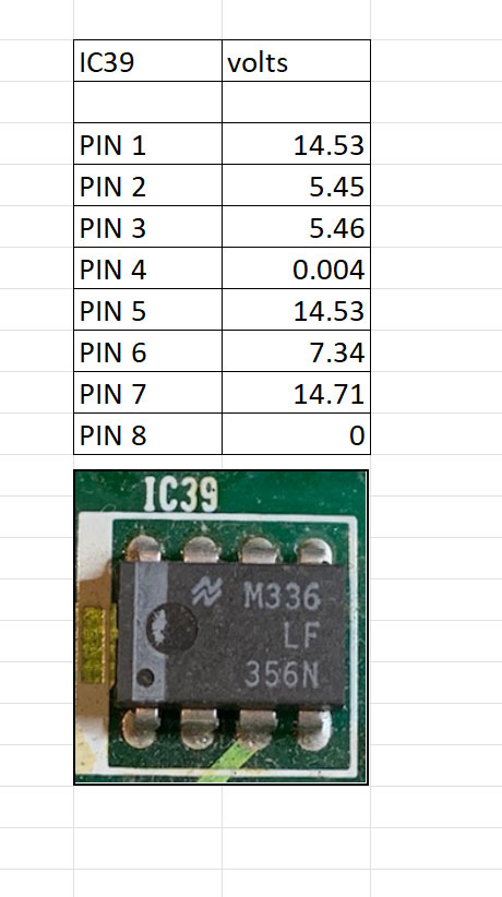
Ok now that makes sense do the same with IC40. We have analogue power since the +15 is there.
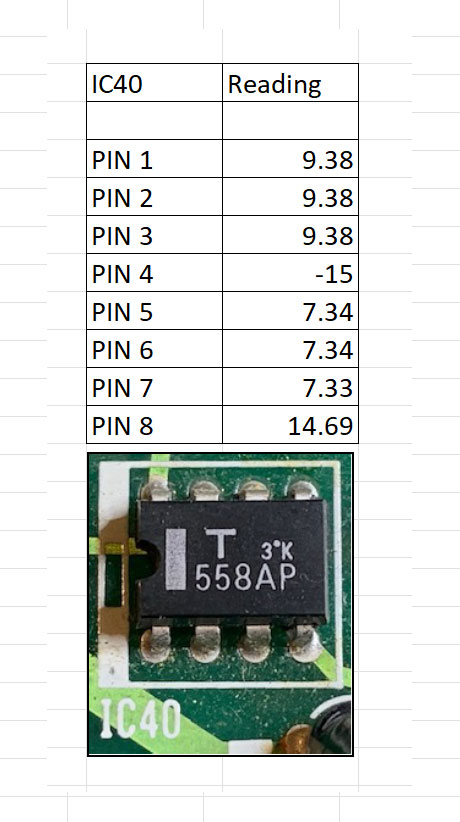
Yep that all seems fine neither 39 or 40 are faulty.
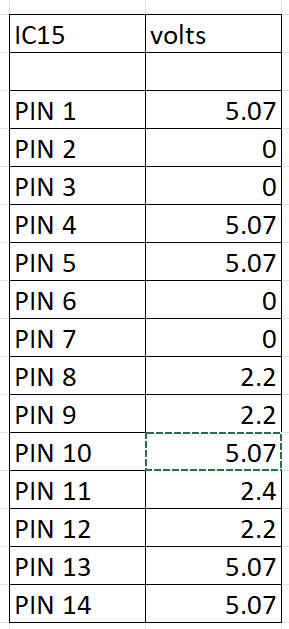
Find IC16 and measure pins 8 and 6

Do the same for IC15. I suspect IC16 but to be 100% you need to see those pins with a scope
Sorry post above this one must’ve not hit reply to you directly
Yeah all three IC14,15 and 16 are suspect but in this case 16 especially so. But can’t be sure till you get a scope. There’s a dual clock signal that gets generated that runs the big FM chips. If you don’t have two clocks coming out of IC16 you have no sound.
Ok cool, i’ll let you know when the scope arrives, says it came to the airport sometime yesterday so hopefully not too long.
Do you know are IC 14, 15, or 16 easy enough to replace if it is them, or am I living a nightmare?
thanks again for your indispensable help Ivan
The parts themselves are easy to get, you go to jaycar has them all. IC14 is 74HC02, IC15 is 74HC74, IC16 is 74HC08. You also buy 14 pin IC sockets the cheap ones. The parts on the machine have a different number but you’ll see the ending is the same which is what matters. What’s not gonna be easy is removing them because of the giant ground plane that’s gonna suck all the heat when you try to desolder so don’t even bother. So we don’t want to remove any chip that we don’t need to do hence let’s look at the scope first.
You need to cut the pins of the old chip using the side cutters then remove the remnants by heating the pads and lifting the remnants with your pliers. Then you need to clear out the holes of solder using desoldering wick or handpump. I recommend you watch some videos on YouTube on this, this particular board is a pain. If you got some old scrap boards get some practice or even order a thru hole practise board which you can find they’re really cheap. Once the holes are clear and you’ve made sure you haven’t damaged any pads you put in an IC socket and solder it, then put the Jaycar replacement in the socket!
Hello everyone, I apologize for resurrecting this topic, but I have a DX9 with similar problems and would like to ask for help.
I recently acquired a DX9 that does not produce sound and displays a “change battery” message on the display.
I searched the internet and only found the schematic drawings of the DX7, the available service manual that I found goes up to page 24 but the schematics of the DX9 are on pages 25 onwards. If anyone has these drawings and can share them with me I would be very grateful.
Well, I opened the DX9, found the 2 4200mF capacitors on the power supply swollen, I replaced them, I did not replace the rest of the capacitors on the main board because in ESR tests they were all perfect, but I will replace them later.
The battery was actually at 0V, I removed the battery, installed a 2032 battery socket, installed a new battery and made sure not to install it upside down. Since I don’t have the electrical drawing of the DX9, I based myself on the DX7 schematic, which has modifications, because in the DX7 after the battery there is the so-called diode D4, but in the DX9 there is diode D2, but following the information, after installing the new battery, I can read 3V on my multimeter on pins 24 of the 2 RAM memories when the DX9 is unplugged from the power outlet. When I plug the DX9 into the outlet I can read 5V on pins 24 of the RAM memories, so I think the battery part is correct now. But when I turn on the DX9 it continues to show the message “replace battery!” Even after changing the battery and being able to read the 3V on the memory pins it continues to display “replace battery!”. I press the MODE key and press the 20 key until I reach the voltage reading and the display shows 0.0v. So the CPU is not receiving the battery voltage value, some analog to digital converter component should receive the battery value and inform the CPU, but this does not seem to happen. In the DX7 schematic there is an A/D converter M58990P that receives the 3v signal from the battery on its pin 4 which is the IN6 of this component, I believe it should be responsible for transforming the 3v signal into digital and informing the CPU, but in my DX9 this chip has pins 5, 6 and 7 grounded to GND, so it has to be another pin, so I need the schematic to be able to proceed correctly. This is assuming that there is no other problem. Anyway, I tried to get the original pressets from the internet at DX9 Patches, I downloaded them and using an interface with the Bomesend software I sent them to the DX9, the website above shows the steps to disable memory protection and enable reception, the DX9 accepts the connection and at the end shows the message “received” on the display, so I believe that it is actually receiving DUMP data from the patch, but no presset name appears on the screen and there is no sound coming from the device, and if I turn the device off and on again it displays “replace battery” in the same way. I may have a problem with the sound generation, but the sound may not be coming out because the memory is scrambled and the DUMP is not being done correctly either, so I first need to solve the problem of the CPU recognizing that the drums are present and make sure that I am doing the DUMP correctly, and only then, when I already have timbre names on the screen “piano”, organ"… etc., I can try to see if the sound comes out or if I need to fix something else related to the sound.
Did anyone understand what I said above?
Does anyone have this electrical schematic containing the DX9 and can send it to me?
Is there anything else I can test?
Thanks,
I got home and went to the DX9. here we go. on pin 2 of the IC8 which is an A/D converter, we have a 10m resistor in series with the positive of the 3V battery. This resistor is altered, I removed it and measured 12.4M, I found it high, so I got some new resistors and joined 3 of 3m + 1 of 1m all in series and got a 10m reactor., put it in the circuit, now I really have 10m between pin 2 and the positive of the battery, but I only read 0.4v on pin 2, then I did a test, removed the 10m resistor and put a jumper, now I have pin2 connected directly to the positive of the 3v battery and I still read 0.4v but I noticed a slight heating of the ci8, so slight that I get confused if it really heated up. so I decide to remove the ci8, after removing it I read 3v on the pad where pin 2 was. This says that 3v arrives at pin 2, but when it is plugged in there is a voltage drop that pulls the 3v to 0.4v. I measured the resistance from pin 2 to the GND pin of the IC with a resistance scale and it is 6M ohms. I measured all the other inputs of this IC and they all have approximately 6M ohms. In other words, all the INs outside the board measure approximately 6M ohms for their GND pins. But when I put it in the circuit, it drops the voltage to 0.4V. I removed the 0.01 capacitor that is there between pin 2 and GND, and it doesn’t change anything. So I believe that the IC has some internal problem that causes the current to be drained to GND. I did one last test, with the IC soldered to the board, I released the resistor to isolate the battery and injected 3V with my bench power supply on pin2 and the negative on the GND of the motherboard. The current consumed by pin 2 is 0.19A, or 190mA. I thought that was a lot for an analog input, right? For this great one, I think I should change the IC 8 M58990P, but I only found it on Aliexpress. I will buy it and pray that it works.