To make a long story short. I just repaired a booting problem that was related to the 3.3V supply.
It now boots and all functions seem to work fine . The only issue is no audio output from the Headphone jack and both R & L channel jacks, I went over all the troubleshooting in the owners manual and even all that looks fine. I updated the firmware, still no change? I would really appreciate your constructive opinions. Tomorrow Ill review the schematics and go from there. Any help would be great.
I am not 100% familar with this beast and I know little about its history.
Thanks all!
Cheers
I knew it was too good to be true… LOL.
Actually I was looking at the schematic just now, but your just too fast for me… Yes getting old… Ill check that out tomorrow. I suspect that power supply supply issue took something out here also.
Don’t go away ,Ill be back !
Cheers ![]()
what you mean - getting old ?!? ![]()
Does that work?
Test entry
• MANUAL MODE:
Turn on the power while simultaneously pressing the
[REMOTE] + [o] (REC) buttons until the “MOTIF XS” is
displayed on the screen and release the buttons.
The following screen will appear and test mode will be
selected.
should show this screen:
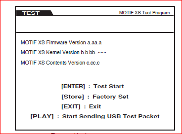
Use the [DEC/NO] or [INC/YES] button to select a test
number.
Press the [ENTER] button to execute the test number
currently selected.
Go to Test 14 - sends a 1kHz tone to the outputs !!
Actually I tried that and and after Test Mode apears in RED letters under the Motif logo, there is nothing else. (I Waited 5 min) . I suspect supply problems in a section. If I have time today Ill get on it. Keeping my fingers crossed.
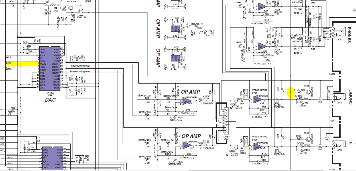
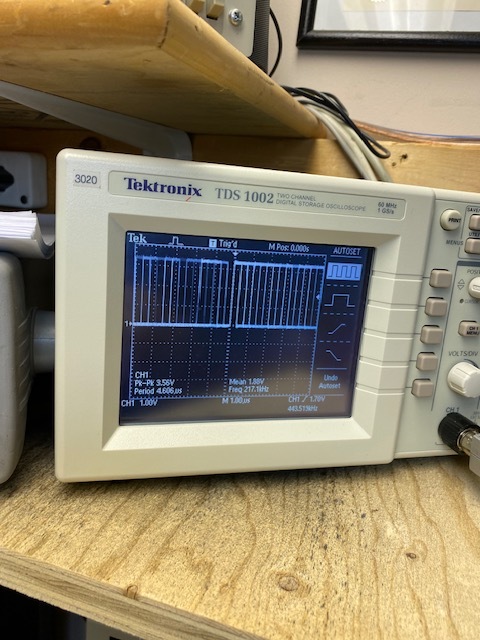
I did a little check today and at the DAC -IC8 pin 6 there is Data .Ill attach a pic on my little synth bench scope.
From there I looked at the voltage level at R82 and it was 4.2V and on TR11 B=0.7V, E=0V, C=0V
Next I scoped the out puts on the DAC pin 20-21-22-23 and I dont see anything ?
Maybe Ill look more tonight. Any ideas?
It’s also bugging me as to why the test menu does not come up.
I did load the demo sequence and tried to run that but still no audio output
TR11 B=0.7V, E=0V, C=0V ← that means MUTE is on … all outputs are shorted to GND.
Have to look at this circuit now (just above IC8) - the 4.2V = MUTE ON is the yellow line at the right - need to study how this works.
What are the voltages to the left of R50 and R59 and at Anode of D14?
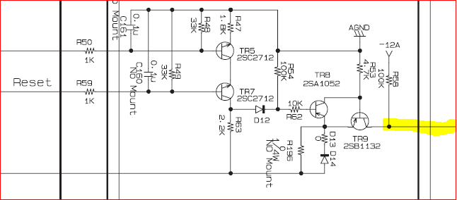
Here is how it works:
Anode of D14 is at +5VD - if TR9 is closed then MUTE is at -12VA. If TR9 is open then MUTE is at +4.2V which is +5VD minus V D14 and a bit through TR9 ← that is what you are reading at TR11.
If TR9 is open then TR8 must be closed meaning that TR5 and TR7 must be open to cause that - hence must check what is at R50 and R59.
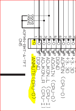
R50 goes here - ANMUTE (CPU-0) which to me reads as “Analogue Mute from CPU-0”
R59 same connector other side being MIDI Reset ?!?
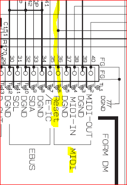
Need to know these signals on R50 and R59 definitively.
Got a little more - that signal off R59 (RESET) comes from the DM board - maybe something stuck here due to the faulty 3.3V being 4.7V … maybe?!
Good day from Canada !
wow, you really impress me and a big thanks, Some of this is a great learning experience for me.
I took some readings with the Motif fully booted up and this is what I see.
R50= 0.0V
R59= 3.3V
Anode of D14 = 4.3V
R58= 11.98 V
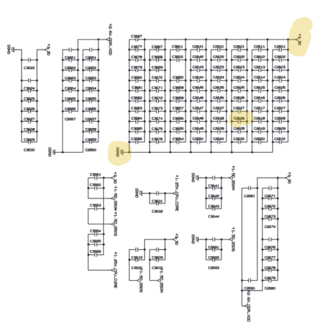
I also see that Analog Mute on pin 1 of CN5 is coming from the CPU and the 1st thing that poped into my head like a nightmare is; that broken Cap that was located under the CPU.“C2628”
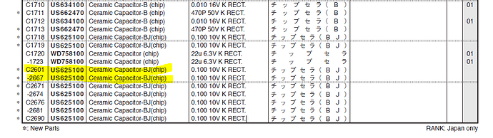
I installed a 0.1uf chip capacitor. I hate the way there is no standard to write capacitor values as I was not 100% sure of what I used was correct. let me know please.
Ill have to pull the DM board to see what pin its attached to. I may be completly off track but better to be sure.
Thanks my friend…
PS. what should I see on CN5 pin 1 .? Do you know.
I just took a look at the MOtif “XS8” DM board and C2628 is located under pins 11-12 of the Master IC. So I no longer think that has anything to do with it… The CPU is completely at the other side on the XS8.
Back to the drawing board… haha
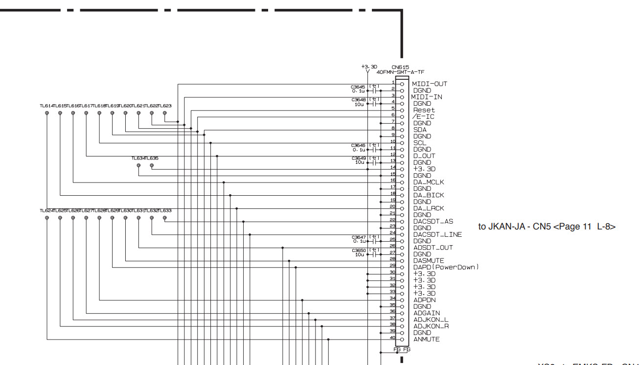
on page 243 CN615 pin 40 I can’t figure where it is going? ( TL624 )
Time to take a break
to be continued tomorrow.
Monday and Tuesday a Holiday . hahahahahaha
THANKS FOR ALL YOUR WORK, my friend.
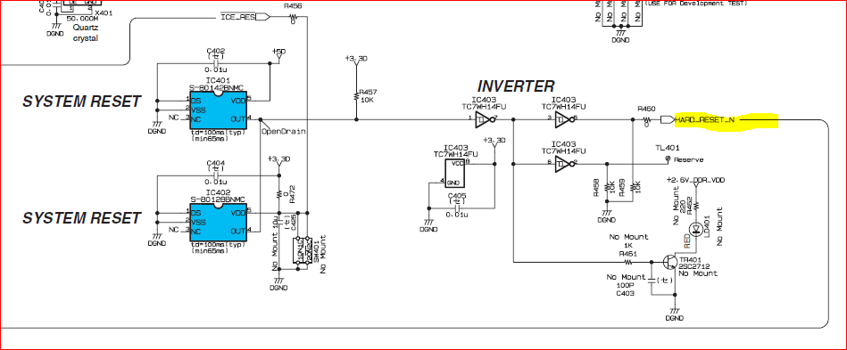
Ill take a look on Sunday but checking the components IC401 & IC402 & IC403 is a bit over my head. I looked at the data sheets and there is some testing info there but I think being so cheap better to just replace them. Problem is Digikey only has IC403. IC401/402 are a three week wait from China
IC 401-402
IC403
What do you think about just replacing?
I don’t really undestand what activates this Reset. (If you can shed some light)
I took a look at the components in this area and I don’t see anything . Last night I went ahead and ordered from China as that is my only option. No one has the parts around me. I hate waiting . F (^&%&^$&$3
Like I said im getting old and running out of time. hahaha ![]()
IC403 is just a simple Inverter - just check the voltage level on either side -voltage levels should always be opposite if working correct - ie if out is around 3.3V (Logic high) then input should be around 0V (logic low)
Just the 5VD input voltage attached to IC401 in combination with the ICE_RES signal going to IC402 … that goes to a DEBUG connector and is currently fixed to 3.3VD.
Any device or system that does sequential work via a given set of instructions needs to be “kicked” to start it’s work at a known point of entry … these RESET pulses are nearly always done via a chip or circuit that has a built in delay to hold the RESET pulse for a short amount of time at a prescribed level (low or high) and then released to start the process.
So - we just need to evaluate why the RESET on the output of IC403 is stuck at the HIGH level.
As per datasheet - IC401 and IC402:
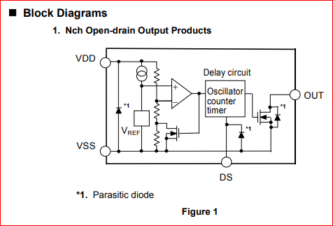
"ULTRA-SMALL PACKAGE HIGH-PRECISION VOLTAGE DETECTOR
WITH DELAY CIRCUIT (INTERNAL DELAY TIME SETTING)
https://au.mouser.com/datasheet/2/360/S801_E-1606001.pdf
And because the two IC’s have outputs tied together they are of this type:
well, Ill see if I can take some readings but I’m quite sure the PCB cables will be too short to turn the PCB as the components are on the bottom side when installed. Maybe I can get something on the back side. I did order the IC’s last night so that might be my only option.
Ill see what I can do and get back.
OK … I added some more above …
Is your guess that one of these IC’s is defective?
Afer looking at the board, I came to the conclusion that trying to take readings can result in damaging the board/ Ribbon cables ect. I will just wait for the new parts to arrive, and just change the 3 x IC’s.
Ill take this moment to thank you very much ! I hope once I recieve the parts you will still take interest in helping or even better , the Motif XS8 will be working.
Cheers for a few weeks.
Take care wernersaurus
Hope it just works … that’ll best outcome !!
Have you looked to see if local is on?