Hi Everyone,
I have a DX7 that used to work fine, but gives no sound after not being used for a year…
I have not been able to determine the cause
this is what I have tried:
The battery is fine it says 3.2 Volt
I thought perhaps the relay could be the issue.
So I desoldered it and made a shortcut like this:
http://fixingelectronics.blogspot.com/2 … ttery.html
however I still get no sound.
when I turn up the volume really high I do hear some sort of very faint tone, it gets higher when i play more notes.
it doesn’t matter wich notes I play. it has nothing to do with the actual sound though.
Can anyone help me determine the cause?
Kind regards,
Steven Gerrits
1 Like
Investigate the DAC? use a scope to see if you’re getting the data into it and audio out of it.
I am borrowing a scope today
hope to have it tonight…
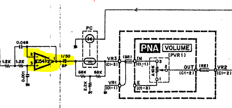
There’s an option for external volume control that fiddles with an opto-coupler device - if that LED does not light you have very very low volume - check the VOLUME Jack socket and/or the opto-coupler device.
As an aside question - when the relay RLY1 was still in - did it actually actuate … did you hear and/or feel it activate?
I did not hear it actuate…
I did test the volune by using a volume-pedal (yamaha)
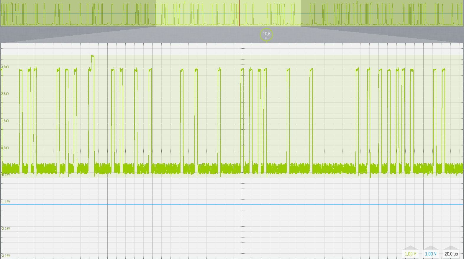
Yesterday I tested the DAC for output.
I had digital output on pins 1-12
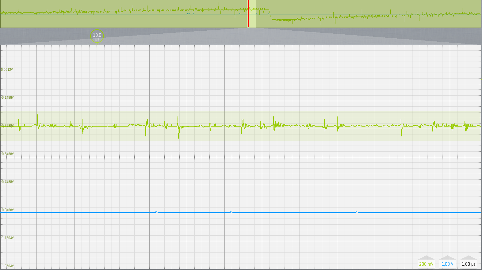
Somebody told me there should be output on pins 18 and or 19
but I only got very faint noise there…
so even if the optocoupler would be out, I should still get signal on the DAC
I’m not sure where to look next…
Any suggestions?
-
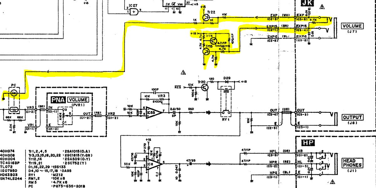
Did you check the voltages on the part circuit I put up ? Check on the VOLUME jack - there should be +15V available on the two pins .
-
If the relay did not actuate (click) then the problem could well be elsewhere …
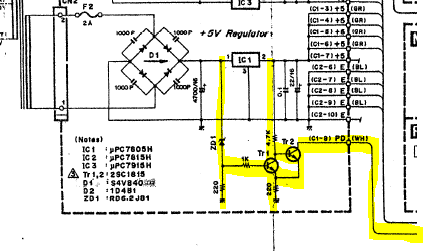
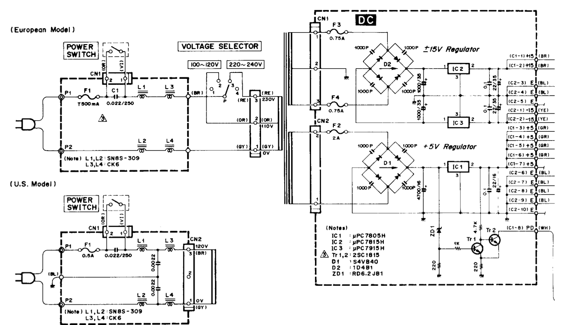
The relay is controlled from the PSU 7805 5V regulator IC1 - the circuit is looking for unregulated voltage (about +10V) and regulated voltage (+5V) … check that circuit as well and let me know.
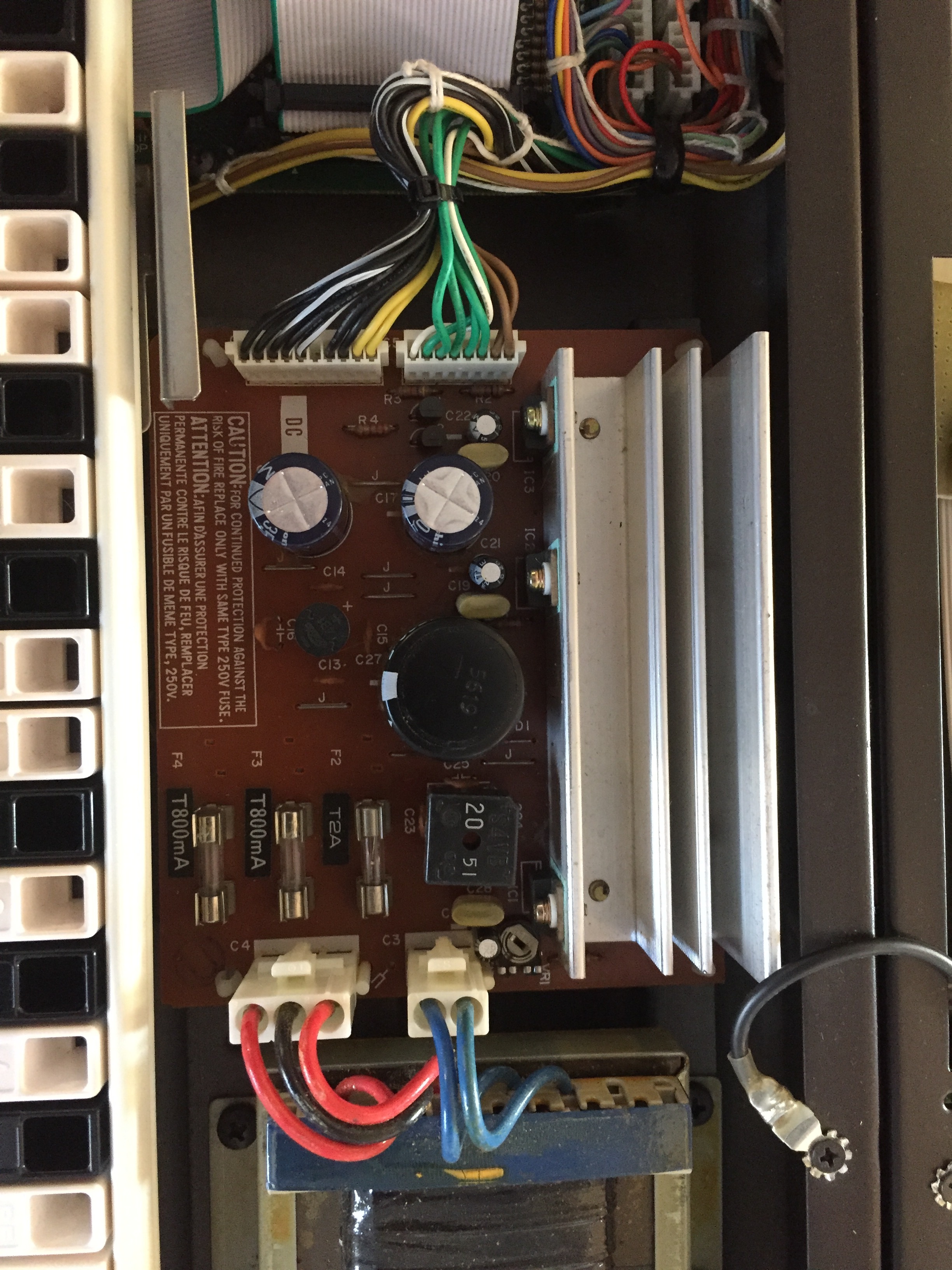
After some additional checking - I am beginning to suspect you haven’t got +5V supply …The DAC using +5V so does the circuit to run the relay. Is that F2 fuse OK in previous entry picture?
Also - did you actually check if you do have all the voltages required - ie +/-15V and +5V ?
before I began to check the DAC I checked all the power-pins on the 2 connectors just left from the transformer. those were all ok
I will check the regulator today and then come back to report.
but if its the regulator, should I not get the regular noise on the output?
both outputs are silent.
on the volume-pedal I have 0,6V on the middle tip
0,2V on the first ring
ground on the shield
Does that make any sense?
I get the same voltages on tr 22 and tr 14
on IC1 I get 12,5V left, 3V middle, 5V on the right pin
In the diagram I can see a D1 and a D2,I only have a D1…
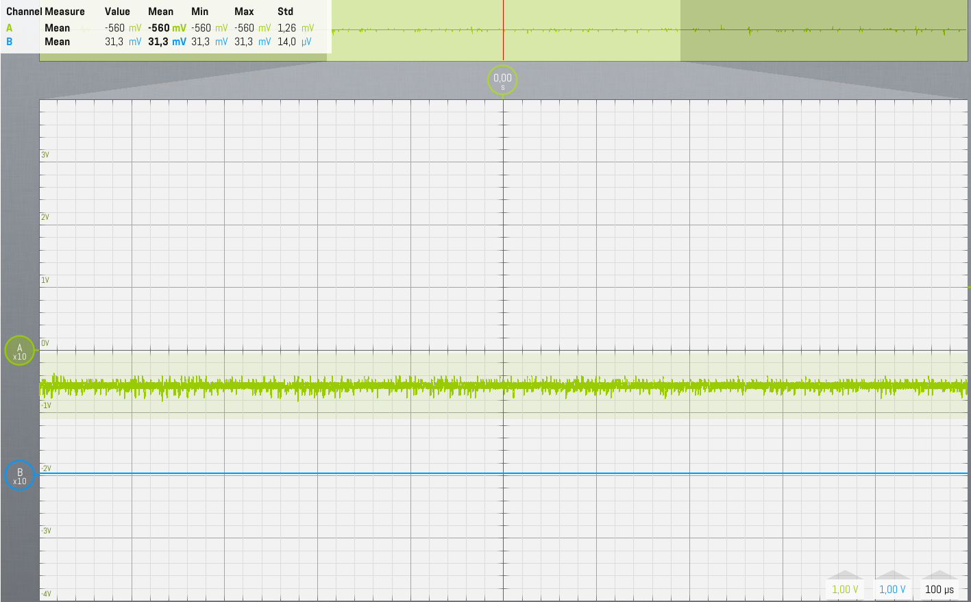
and here are the scope pics from the DAC
pins 1-12

pin 18

pin 19
I played a init. sound on c3 here, so should get a sine
D1 is the bridge rectifier - the black square next to the fuses - that is OK. But the voltages on the VOLUME jack socket are not right.
For the LED inside the opto-coupler to light up you need at least 1.2V on the emitter of Tr22 and an additional .6V on the base of Tr22 for Tr22 to open up fully and light the LED - so I would expect approx 1.8V on the the ring of the VOLUME jack socket.
Have you checked the +/-15V ? If no +15V then the tip on the VOLUME jack will be close to 0V, the LED wont light up - hence no volume and the relay coil is on the +15V as well - hence relay not activating - does that make sense?
certainly that makes sense.
this means certain parts of the mainboard have a good voltage and other parts dont.

After studying this page, i found that the black wires are 0
the brown are +15V and the green are +5V which is is what I measure
well: 14,88 V and 5.15V
Having lost voltages on parts of boards is certainly possible.
So - now that we know we are having +15V, -15V and +5V - can you find Tr22 and see if it has +15V on the collector? Also, have you got +15V on the Cathode of D29 (the diode across the coil of the relay)?
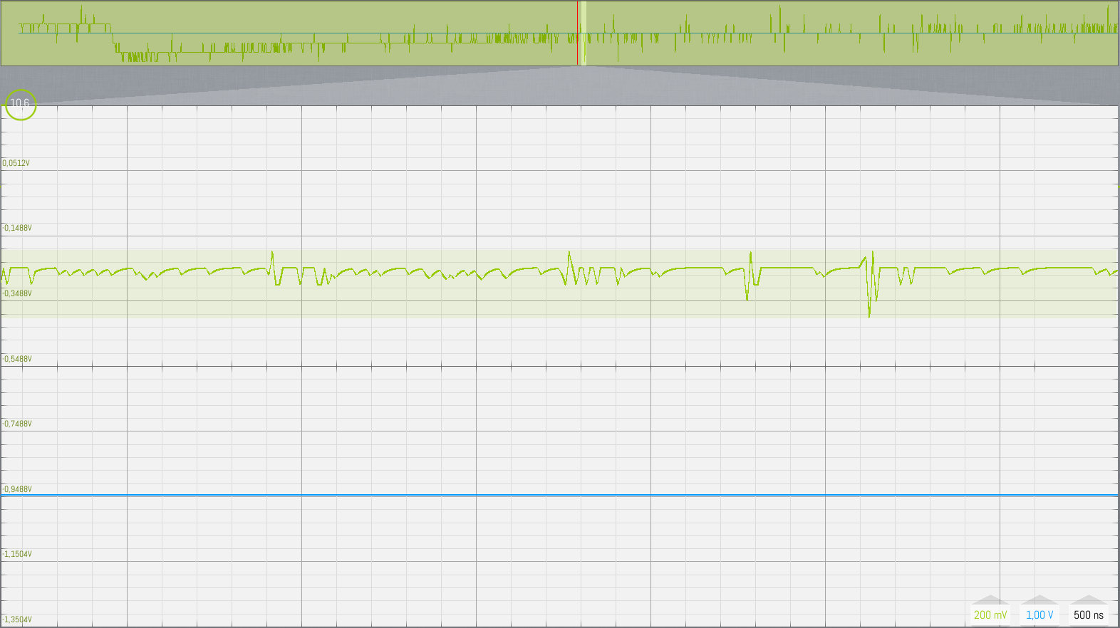
Also - with the scope - what can you see in PIN 1 IC54 - the opamp just before the opto-coupler?
TR22 has -0,6V on the collector
D29 (and Relay has -0,6V)
opamp pin 4 has -15V all other pins have a similar output:

I measured pin 4 on a couple of other opamps to see if they got power.
I did not measure a voltage on pin 4 on opamps IC53, IC40, IC8, and IC45 and pin 7 of IC52
I did have power on opamps IC43, IC57, and IC55
on visual inspection I see all the IC’s not working are on the same conducting plane.
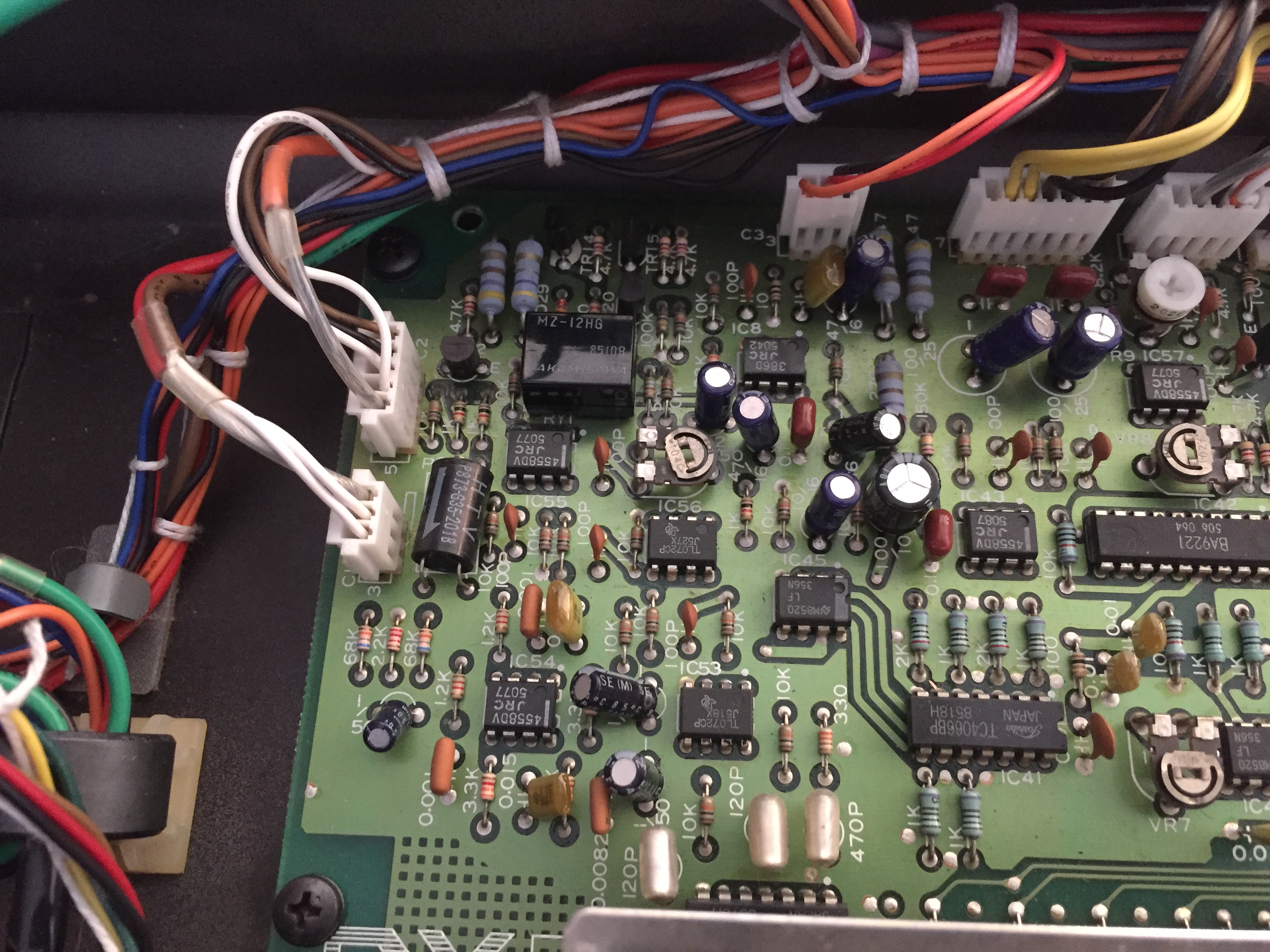
Looks to me like no +15V - have you checked PIN 8 on the opamp - that should be +15V
in this orientation should it be
4321
5678
?
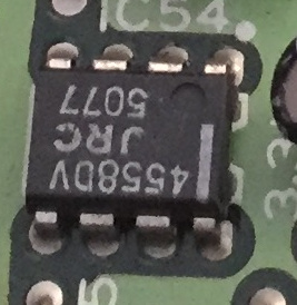
yup - standard 4558 chip - pin1 at the dot then go counter clockwise - pin 8 is opposite pin 1, Pin 7 is opposite pin 2 and so on
pin 8 should be +15V
well, I only get 15V on pin 4
reading the circuit-diagram I cannot make out where the voltage should come from.
Could you point me in the right direction with that?
you mean -15V right - if that is the case we have to find the missing track or contact or what ever …