-15,27 Volts on pin 4
0,63V on pin 8 (but that would be the signal you see in the scope above)
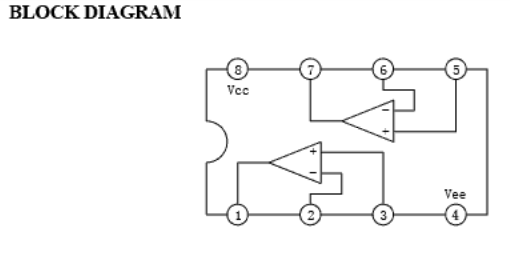
that is how the 4558 opamp internal look like
For me it is getting somewhat harder now - for you, you now need to take out that board and slowly follow the connection(s) that go from Pin 8 of that chip. Have you got a meter than can be selected to “beep” on continuity?
If so - first check the brown wire at the power supply for continuity to the brown wire(s) on that board …
Then you have to trace that PIN 8 of that chip backwards
I cannot see it on the PCB diagram - it is a PDF made from a TIFF - impossible to read.
I can only just make out CN4 where the power is attached (yellow) and the 8-pin opamp we are seeing (yellow)
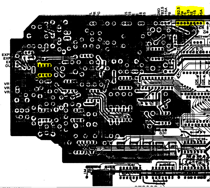
It is really up to you now to trace that PIN 8 backwards … sorry ![]()
I have been following the discussion and wanted to let you know that those ic’s that have no voltage on pin 4 are connected to the ground plane on the board. They will be 0 volts when read with a voltmeter.
Before you remove the board i would check the voltages at the DAC. There was data coming into the DAC and almost no signal coming out. This where i would start.
Cheers
Pat
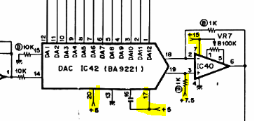
IC40 is different - that is the summing amp for the DAC and is GND referenced because the DAC chip only runs on +5V. BUT - it seems he doesn’t have +15V hence that IC40 still would not be working anyway - or alternatively that section of the board still has +15V but the output section has not.
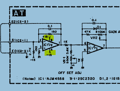
We know the relay didn’t work (+15V required) but he replaced that with a bridge, and the expression does not work (+15V required) and is kept a lowest volume.
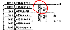
We are looking at the 4558 opamp chips and they are +/-15V - pin 4 -15V pin 8 +15V (see below)
Thanks for the clarification wernersaurus. I guess i wasn’t following that closely. ![]()
Cheers.
Pat
Kropjesla - how you’re going so far ?
I’m sorry, I’ve had some other things to do here.
I’ll try and take the board out today or tomorrow
Ok here I am again, and this is what I found.
The pins to IC5 are connected to the voltagesupply-plug as illustrated.
I measured the connection to be 0.01 Ohm which seems good to me.
I also will post some more pics from the bottom of the board for reference.


Something just is not what I am expecting!! The +15V you marked in RED goes directly to the relay RLY and its coil reverse shorting diode - so relay should have worked if +15V is available at the C4 connector.
If you use Ohm meter and measure from C4 pin 1 + 2 (brown wires) to each PIN 8 of IC53, IC54, IC55 and IC56 ( see back up at your post #15) - they all should be 0 Ohm ! They are all 4558 and TL072 opamp ICs and all have PIN 4 = -15V and PIN 8 = +15V.
also - can you apply power to the board and give me the measurements at below points please
I started by connecting the powerplug to the board measuring the points in your picture. I get -15.2V on the left side (in this orientation)
and 0,6V on the right side.
I suspected a bad solderjoint, but when I use an Ohm meter I get 0 Ohm between the pin from the connecor and the bottom of the board. (different joints)
So I also measured the Poweroutput of the plug and it was correct meaning -15,2V on Yellow and 14,8V on brown.
but as soon as I plug it in the power on brown (being the right side) drops to 0,6V
My conclusion at this point is that some component is “eating” away all the power
anyway the resistance of pin 1+2 (soldered together) and IC53 pin 8 is 0,2 Ohm
IC54 0,2 Ohm
IC55 0,2 Ohm
IC56 0,1 Ohm
AHHHHA!!!
You DON’T have +15V at all !!!
Go back to POST #13 and check the +15V Regulator IC
I’m not sure what you mean because when I measure all the output-pins C5 and C6 everything is good meaning: from top to bottom:
C5
pin 1 brown 14,9V
pin 2 brown 14,9V
pin 3 - 7 green 5,1V
pin 8 white 1,1V
C6
pin 1 yellow -15,2V
pin 2 yellow -15,2V
pin 3 - 10 black = nul
if that is the case than shouldn’t IC 1-3 be ok too?
(it is almost impossible to reach IC 1-3 so I am afraid I might short something out)
Your assumption that something is “eating” away all the power may be correct.
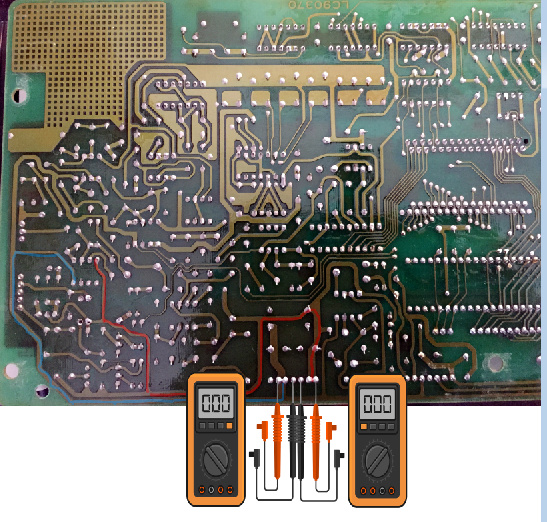
To verify can you use first disconnect the power connector at C4 on the main board.
Use your ohm meter and take a resistance reading on the main board on the solder side of the power connector between the +15v circuit and the ground or common pin. See the diagram that werner posted with the meter diagram. If you get a low resistance reading then there is a short circuit on the main board.
If the resistance reading is initially low and then starts to increase then that indicates that the main board is ok and the fault is in the power supply.
Hope this helps.
Pat
OK so I measured the resistance between the power-connector pins
I get readings round about 2KOhm between the power and 0 pins but my meter is not entirely precise.
no shorts though…
So the problem appears to be the power supply. One of the first things i would do is replace all the electrolytic capacitors. The synth is over 30 years old and the capacitors have probably dried out.
The factory supplied caps are rated at 85C and whenever i replace caps i use ones rated at 105C.
Like werner said in a prior post the voltage regulator may be at fault but they are pretty robust devices with thermal and short circuit protection.
Pat
Pat - this is going to be a long haul for Steven … as per his comments in Post #30 +/-15V is OK with C5 disconnected - meaning the Power Supply itself is most probably OK. So the problem is ONE component on the main board that kills off the +15V because he stated in post #30 “as soon as I plug it in the power on brown (being the right side) drops to 0,6V”
So first thing to go for is that 100uF/25V capacitor just at the connector
which is this guy here .
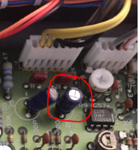
If that doesn’t cure the problem then Steven has to remove any component hanging on the +15V rail until the finds the bad one (excluding resistors maybe) !?!? ![]()
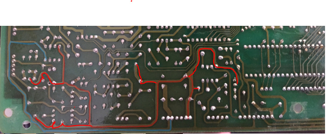
Maybe there are jumpers on the circuit board the continue the +15V rail to various places on the board - removing one-at-a-time can help narrow down the area of problem.
If you look at this section and follow the +15V rail there are finite places - but +15V is present at other points on the board so there must be jumpers at various places …
I’m not a wizard with the soldering iron, so desoldering lots of components seems a little overwhelming.
but I guess there is no other way at this point?
Werner - I had him check the resistance between +15V and ground/common at the power connector on the main board. There does not appear to be a short on the main board. That’s why the power supply is suspect. It may not have enough current to supply the main board due to failing capacitor or voltage regulator.
A very rare possibility is that a component is breaking down when the 15V is applied to the main board. In which case he will have to un-solder components one at a time.
Steven - You mentioned that your meter is not precise. Can you tell us the make and model please?
Do you know some one locally who has good soldering skills?
Pat

this is what I have…
I do know someone that has soldering experience but he’s a tech who works on big machines around the world, I don’t want to bother him too often…
I’ll try and start with that first capacitor and sse how it goes.
not sure how that will work though…
when I measure it with the Ohm-meter it says unmeasurable (while it is still in…)
that would mean it is not leaking current, or is that too simple?
The meter you have is not bad and should get the job done.
Just be careful to not apply too much heat for too long or you may end up lifting the pcb trace.
You can’t measure the capacitors in-circuit with an ohm meter. All the surrounding circuitry will affect the reading. If you want to test electrolytic capacitors in-circuit you would need an ESR meter (equivalent series resistance). It measures the internal resistance of the capacitor ( which will increase when the capacitor fails).
Doing a search for ESR METER on Ebay should find you some. They’re not too expensive.
Pat
1 Like