Steven,
no need for an ESR - this will just confuse you and not help the situation.
We know there is a short circuit - so let’s find it … one step at a time …
when I desolder the capacitor, should I install a new one? or should I first try to hook up the board again to check the voltage?
(if I have to get capacitors, resistors etc I have to drive to a nearby town so it takes a lot of time to do so for all the parts…)
… it’ll work without the capacitor - no problem to try - if the DX7 fires up you are OK to add the cap later …
unsoldering the capacitor did not fix the problem (as expected because the resistance was unmeasurable) voltage still 0,6V
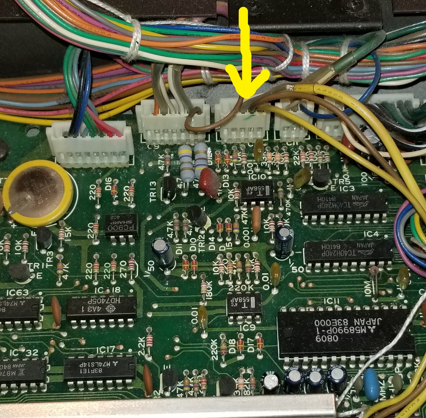
if i follow the connections there’s a transistor and a resistor (resistor measures 2650 Ohm across which is within its tolarance) should I unsolder the brown capacitor too?
Steven,
Yes - take out the brown one as well, components with two legs are easy to remove and re-insert - components with 3 and more legs are difficult.
I knew this will get tedious … difference between a workshop environment and DIY (absolutely NO offence intended).
You also should investigate whether you can do a “divide and conquer” - meaning if there is a way to separate two parts of the +15V supply chain on the DX7 main board.
As an aside note:
I would now take a benchtop power supply and attach to the board and see what the current draw is - and possibly even allow a huge current, more than the on-board regulator allows to see if something is getting really hot --> that’ll be the faulty part.
Also - taking a big resistor and load the power supply , without the DX7 main board connected, to make sure it can deliver the required current. You think you could get your hands on a 20 Ohm 10W or 5W resistor ?
I’ll have to get back on that one. I’ll see what I can do…
Steven:
I noticed on the schematic that the +15v and -15V leave the main board for the after touch circuit. To eliminate the possibility that the after touch circuit is the problem i would disconnect the circuit at the main board connector. Then power up the synth and see if the +15v is still there.
Pat
allready done that but thank you! ![]()
tomorrow at 11 AM a friend of mine will help me out.
(timezone UTC+2)
hello, here I am again with a lot of news:
I started out desoldering components on the mainboard to see if the voltage would come up again, but it did not. after desoldering and resoldering about 6 capacitors and 2 IC’s I decided to try PPD’s suggestion to try a different powersource to see what would happen.
when I tried to put 12 volts on the 15volts pins the voltage did not drop!
so the power-supply was the suspect
I desoldered all the capacitors and checked them.
also the 15V rectifier.
it was fine.
I ended up getting 3 new capacitors (the big ones) and getting 3 new triacs.
after that the voltage readings were 5V, -15V and 25V
that was strange.
I checked the smaller capacitors but they were fine.
I decided to put the board in and see what the voltage readings would be then.
they turned out to be exactly right!
+15V and -15V
there seems to be some sort of interaction between the motherboard and the powersupply.
strange…
anyway I didn’t get any sound yet
but when I use the scope again on pin 19 of the dac I got a sound wave.
it wasn’t a sine but still
The problem now is that both display and leds give no readings
oh they do lit up, but I can’t make anything of it…
UPDATE
the unit has been on for half an hour and the display as well as the LED’s are back.
I even get sound out of the unit, but it is very faint and very distorted.
Suggestions please…
Good to hear your making progress.
I’m a little concerned about the 25V reading you got before you connected the power supply to the main board. I would do a visual check of the power supply PC board to make sure there are no solder bridges.
The +15V should not change very much whether the main board is connected or not. What is the part number of the +15v regulator that was changed?
I know you said the backup battery was reading 3.2v after you took it out of storage. Perhaps the sound tables are corrupt in memory. Do you have a plug-in sound cartridge you can use?
Pat
the triacs I changed were: 7915, 7815 and 7805
We (a friend with a lot of knowledge of electronics and myself) did inspect all the solder joints on mainboard and power-board. we resoldered most of the power-board.
I do have a cardridge with sounds I can load in…
I have to do that every time I take out the board…
Those are the correct voltage regular parts. If you’re comfortable with the power supply repair then i would continue on with tracing the signal from the DAC on to the output. Make sure you have correct voltages near the DAC. You should be getting a signal of about 1 to 2 volts peak to peak at pin 6 of IC40. For some reason the sound file you attached won’t play??
Pat
well it turns out the 25 (even27) Volts are on some places on the mainboard also, so I will go back and try to fix the voltage issue.
not sure how though…
There is the possibility that the voltage regulator is shorted, the wrong part may have been installed or that your meter is not working properly.
I would not power up the synth anymore until you have verified that you are getting the correct voltage. Do you have access to another volt meter that you can borrow and verify that it’s reading is similar to your meter?
Can you provide me with the actual part number printed on the regulator?
Pat
I was just thinking…
since i got a big distortion on my output.
is there a way to determine if the operator-chip still is ok? (IC36)
because if that one is failing I might as well give upon this one.
The operator-chip works on 5 volts, so it should be fine…
I know the envelope-chips works because I can hear the sounds changing over time (attack etc)
furthermore
Chips IC35, IC44, IC41, IC45, IC52, all use +15V, so they are the main suspects for the distortion.
but there is a voltage regulator on the mainboard (IC56 an IC57) they could be feeding some of the 5V chips as well
Steve:
I would first verify that the +15v is ok before moving forward. I know you did a visual on the power supply PCB but one other item i would like you to check is continuity from the common pin of the +15V regulator to the common on the PCB.
You are correct about the +15V (and also the -15V) causing distortion. Those voltages are used for the analog circuitry.
Let me know what you find with the power supply.
Pat
turns out I was not entirely correct about the voltages.
I get 5V on green (=ok) 7805 = ok
15V on brown (=ok) 7815 = ok
-25V on Yellow (not ok) 7915 = not ok
pin1 on 7915 is connected to common
at this point I’m not sure how to fix the issue.
could it be I was just very unlucky to get a faulty 9715?
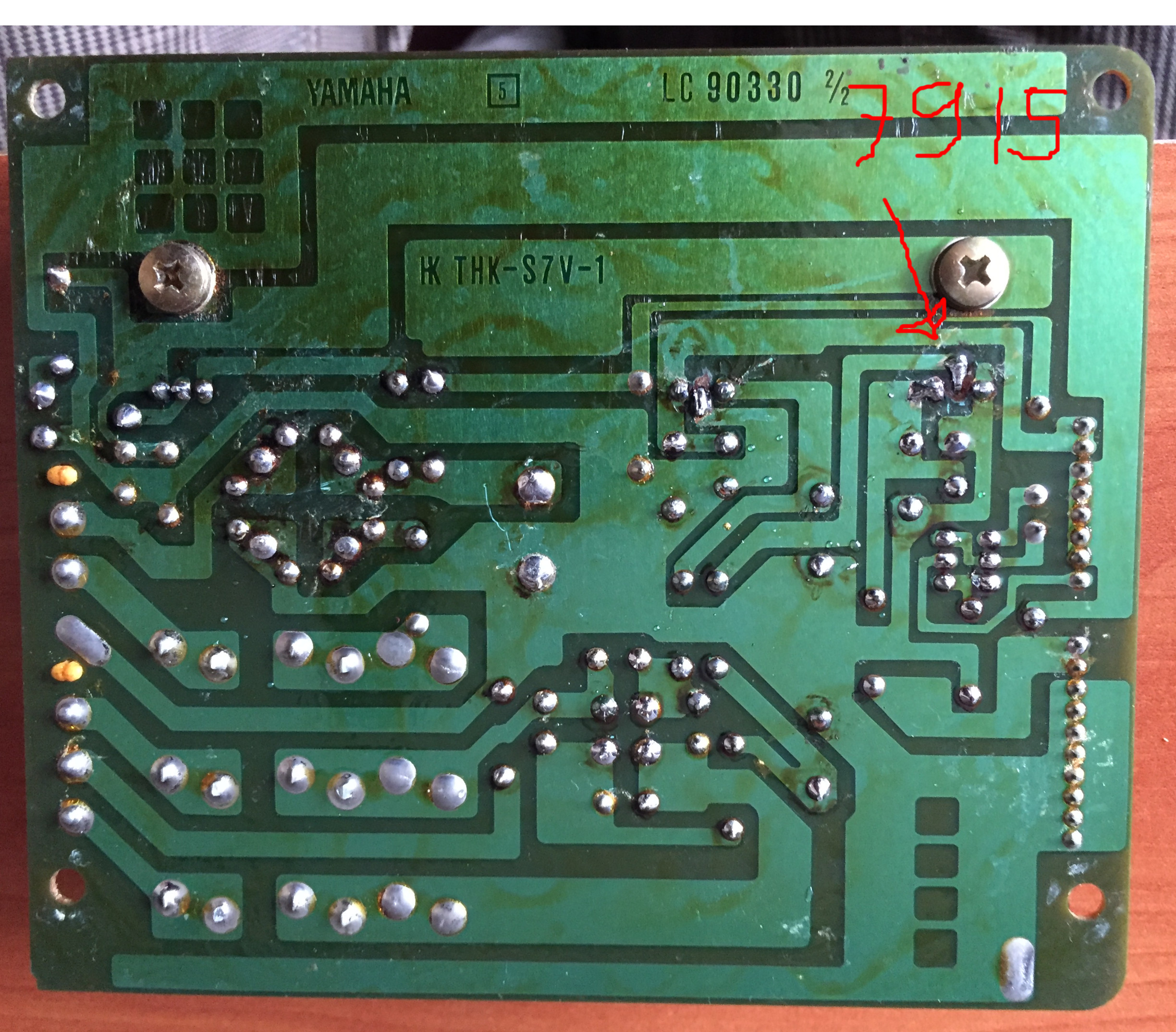
Take some resistance readings on the power supply. Measure resistance between the yellow dots you should get close to 0 ohms. That ensures that the voltage regulator is properly grounded.
Measure resistance between the orange dots. You should get a very high resistance. This is checking for a short between the input and output of the voltage regulator. Verify that it is a 7915 part.
The part could also be a fake. But fake parts are usually made to resemble the more expensive or obsolete components.
Pat
