78xx regulators and 79xx regulators have different pin allocations (just to confuse everybody)
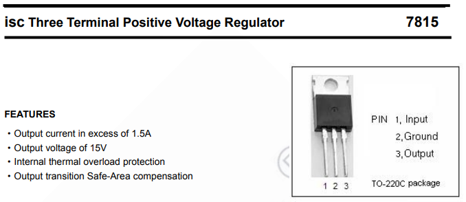
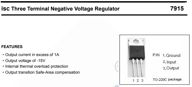
78xx regulators and 79xx regulators have different pin allocations (just to confuse everybody)
I bought a new 7915 and changed the small capacitor next to it. still -25V
I’m lost…
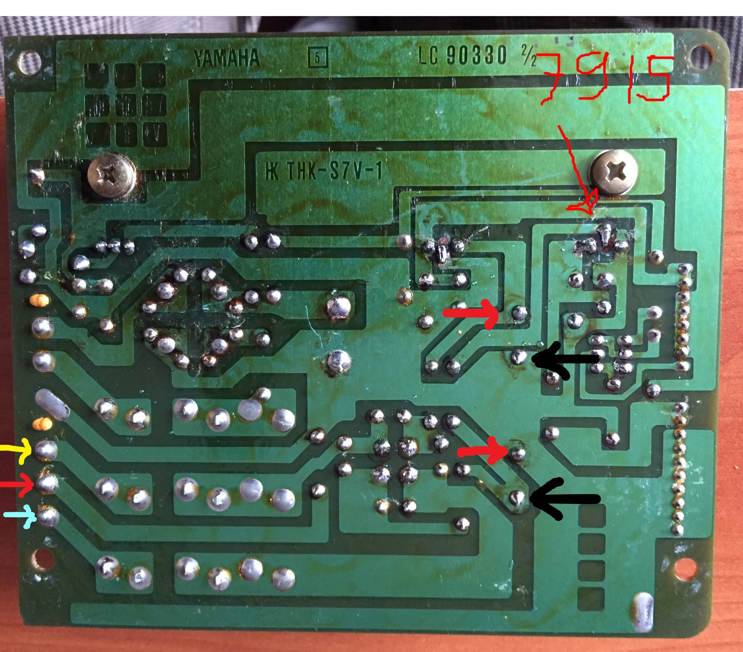
Can you power up the power supply ( with the C5 & C6 connectors removed ) and take some readings.
With your meter on AC volts what is the voltage between:
The red arrow and the yellow arrow on the lower left of the board?
The blue arrow and the yellow arrow on the lower left of the board?
Switch your meter to DC volts.
With you meter connect the black lead to the black arrow and the red lead to the red arrow:
What is the voltage across each those two capacitors?
When the voltage regulators were replaced the plastic insulators and the thermal/insulator pads were re-installed?
When the voltage regulators were replaced the plastic insulators and the thermal/insulator pads were re-installed?
yes the isolators are still in.
25V AC between yellow and red
50V AC between yellow and blue
(the 5V circuitry has 12V AC)
unfortunatly the main fuse broke as i accidentally touched the ground.
so I have to do some other measurments when i get a new one
I’ll be back
I measured the top capacitor (in your picture) which is the 15V side
the voltage across is 34,2V (black lead is the common in my meter)
voltage across bottom capacitor (which is the -15V side) is 34,4V
(which is -34,4V if the common equals the common on my meter)
so I’m not sure what causes the problem.
the only thing I did not change are the bridge rectifier and the 140K50 capacitor
(and the small ceramic capacitors beside the bridge rectifier)
I did measure those and they seem fine
the bridge rectifier gives out 503 - 530 on the conductive directions and inmeasurable in all non cunductive directions. (which i think would be correct)
these voltages are the input of the regulator, not the regulated output.
the regulated outputs are accross C19 and C22
you’ve measured 25Vac at the input between yell and red.
so you have (25-0.7)*1.414 = 34.36V filtered this is near that you have on the cap.
thank you for your reaction genesis.
Yes you are right. The problem we are trying to solve here is why the output after regulator 7915 is -25V in stead of -15V
if you have any insights, please do share!
this is what you measure accross C21?
check carefully the board for crack and copper trace break of the voltage regulator ground.
but the 34.4V you have measured is for the positive supply, not the negative
across C21 15V
across C22 -25V
I measured 34,2V for possitive supply
and -34,4V for negative supply
so the positive and negative rectified voltages are ok.
check carefully if the ground trace going to the 7915 is not broken
0,1 Ohm seems ok to me
so if you have 34V in and 25v out without any trace break, only the regulator could be the culprit. it’s a linear Vreg and even with bad capacitor and no load it will go in regulation.
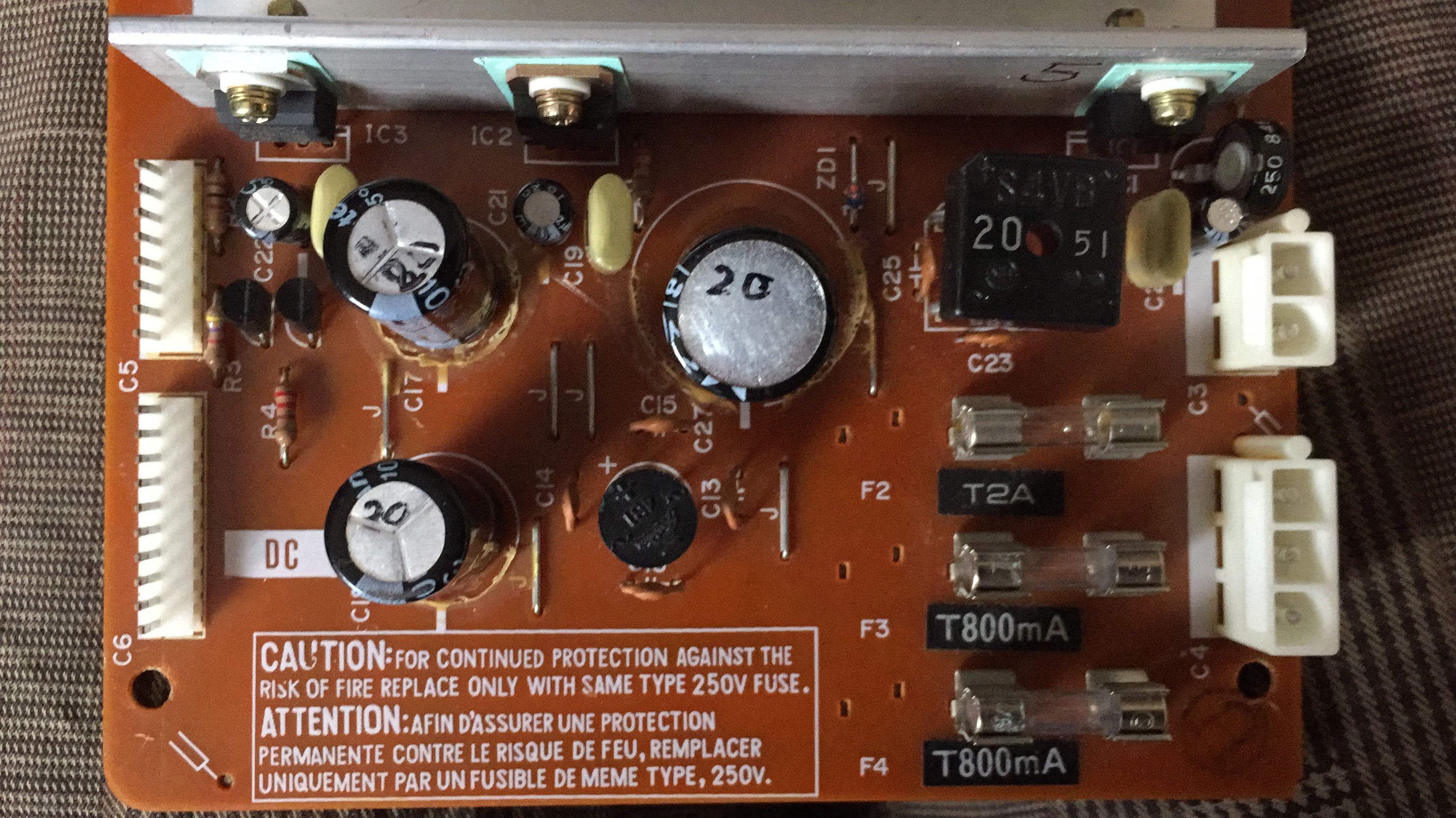
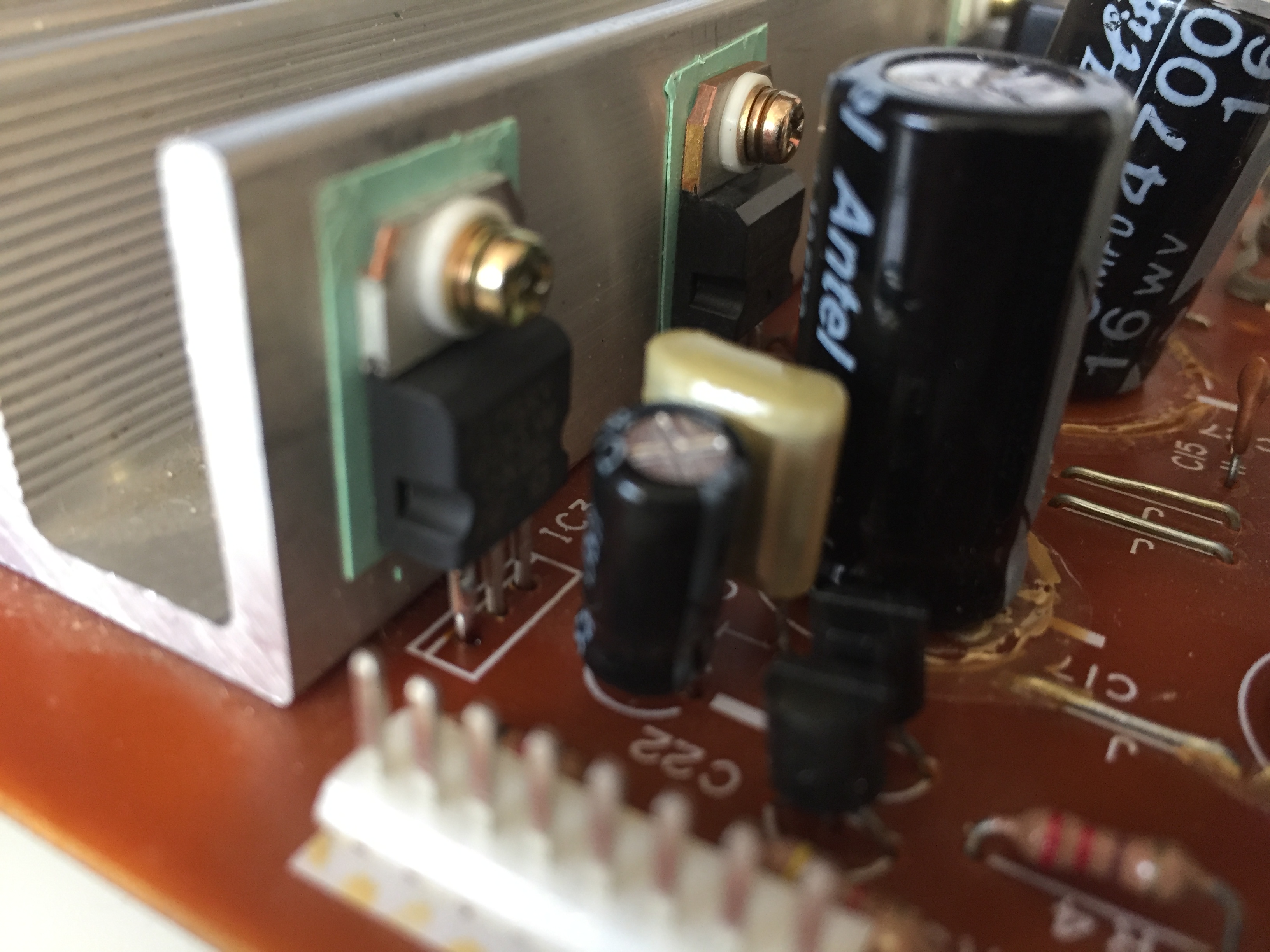
can you take a picture where we can see the IC3 Vreg TO220 package markings?
I’m not sure what you mean, Do you mean the regulator?
that you can see in the picture above, it is from my power-board
does this help?
unfortunately no, I would like to read the marking on the body of the component like this:
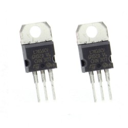
and the picture must not be blurry
here they are both
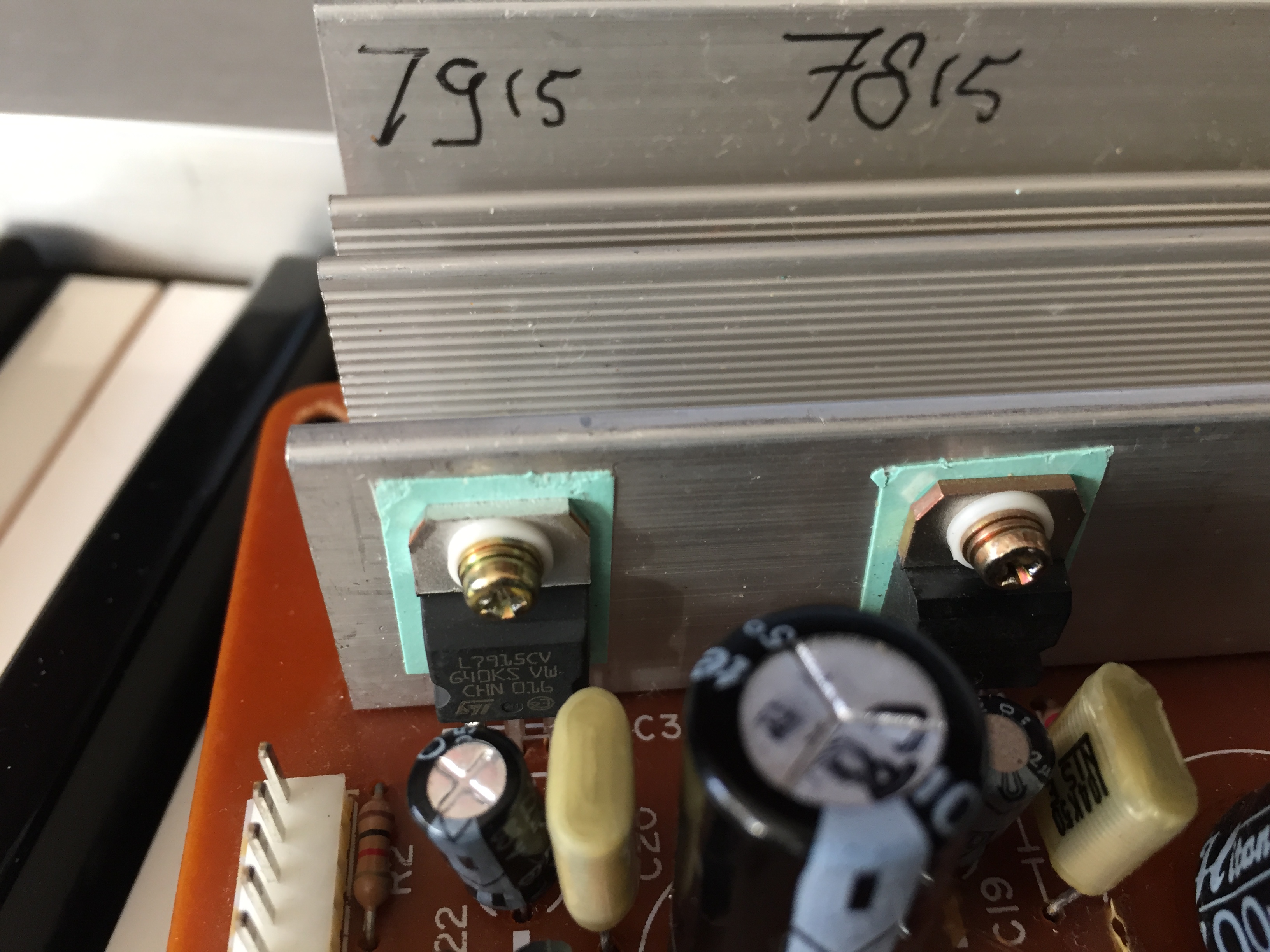
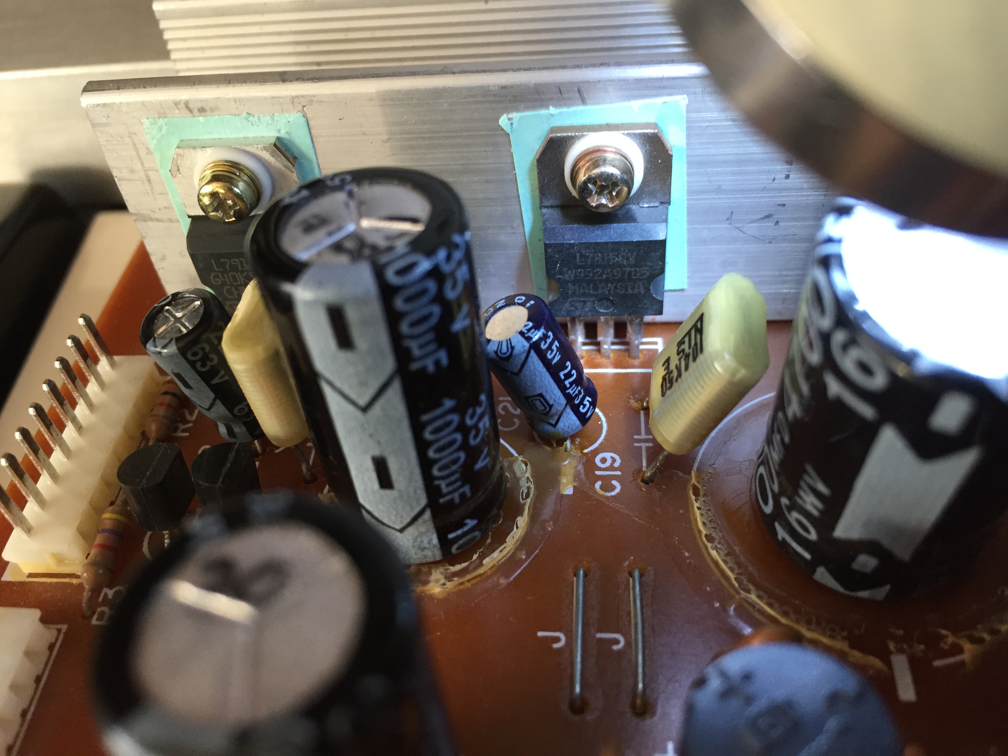
why are you looking at the 7815? that one gives out the correct voltage…
ok it’s a strange behaviour.
do you have another 7915 ? but they are very strong components. it’s very hard to kill them.
nothing is getting hot?
well, I have 2 they both gave out the same readings (and they are new ones too)
hot? no not really
you confirm the test are made with the PSU board disconnected