how about the -15 V?
Hi everyone,
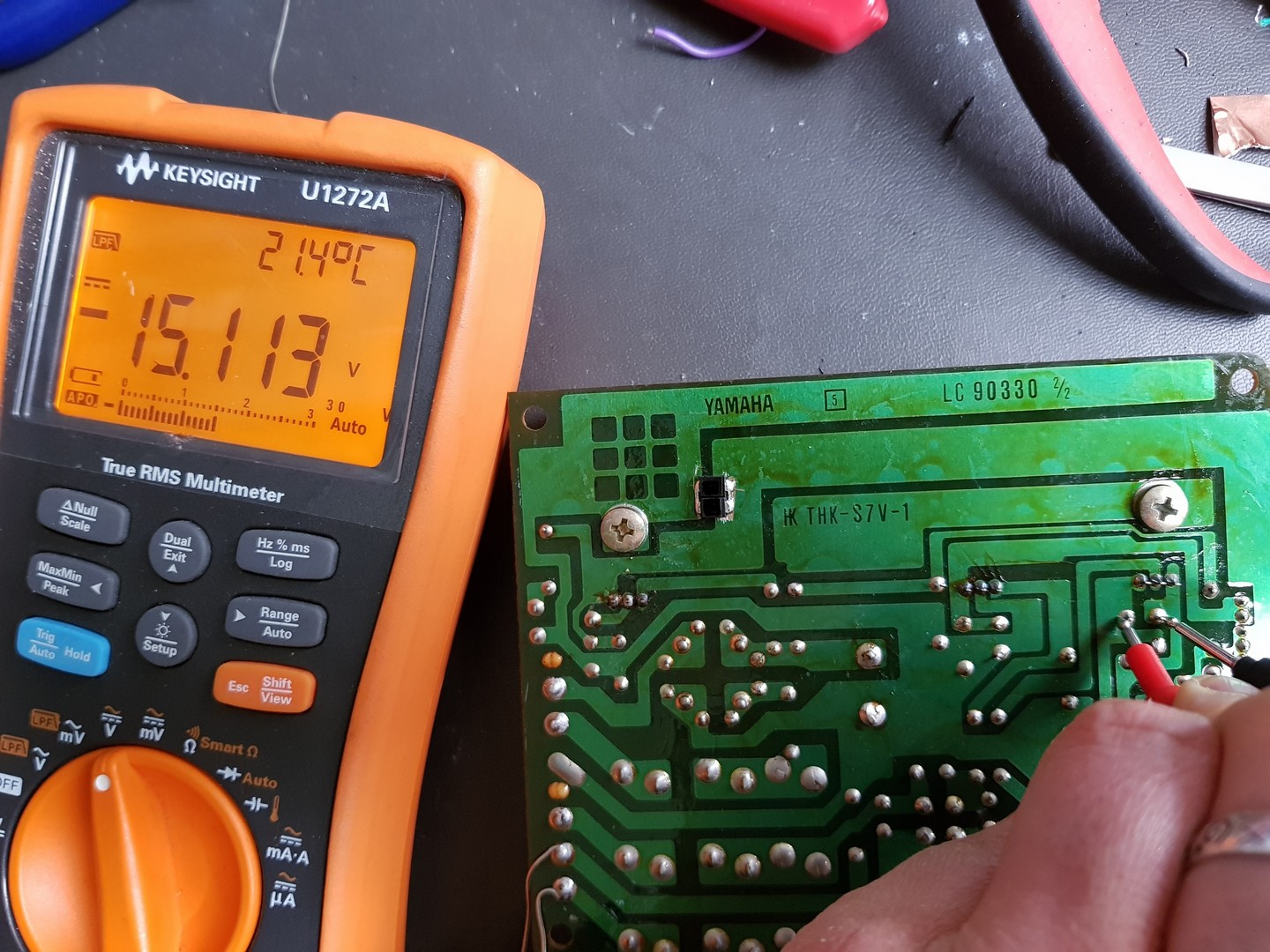
I’m still struggling with the 7915 output voltage.
according to various data-sheets the max input voltage of the 7915 is (depending on manufacturer) between 30V and 35V
so my 34,4 Volts might just be too high.
I will try to put a 7924 before the 7915 to see if that works.
I’ll get back to you as soon as I have tried that.
(still not sure if there is a fault in my motherboard though, n with case the synth might be beyond repair…)
Hi everyone, here I am again.
Its been a while, but I managed to get the right voltage on my output board.
the bridge was giving out 34V but the 7915 has a max input voltage of 35V
I think that’s why I burnt 3 of them it was just too close to the max range.
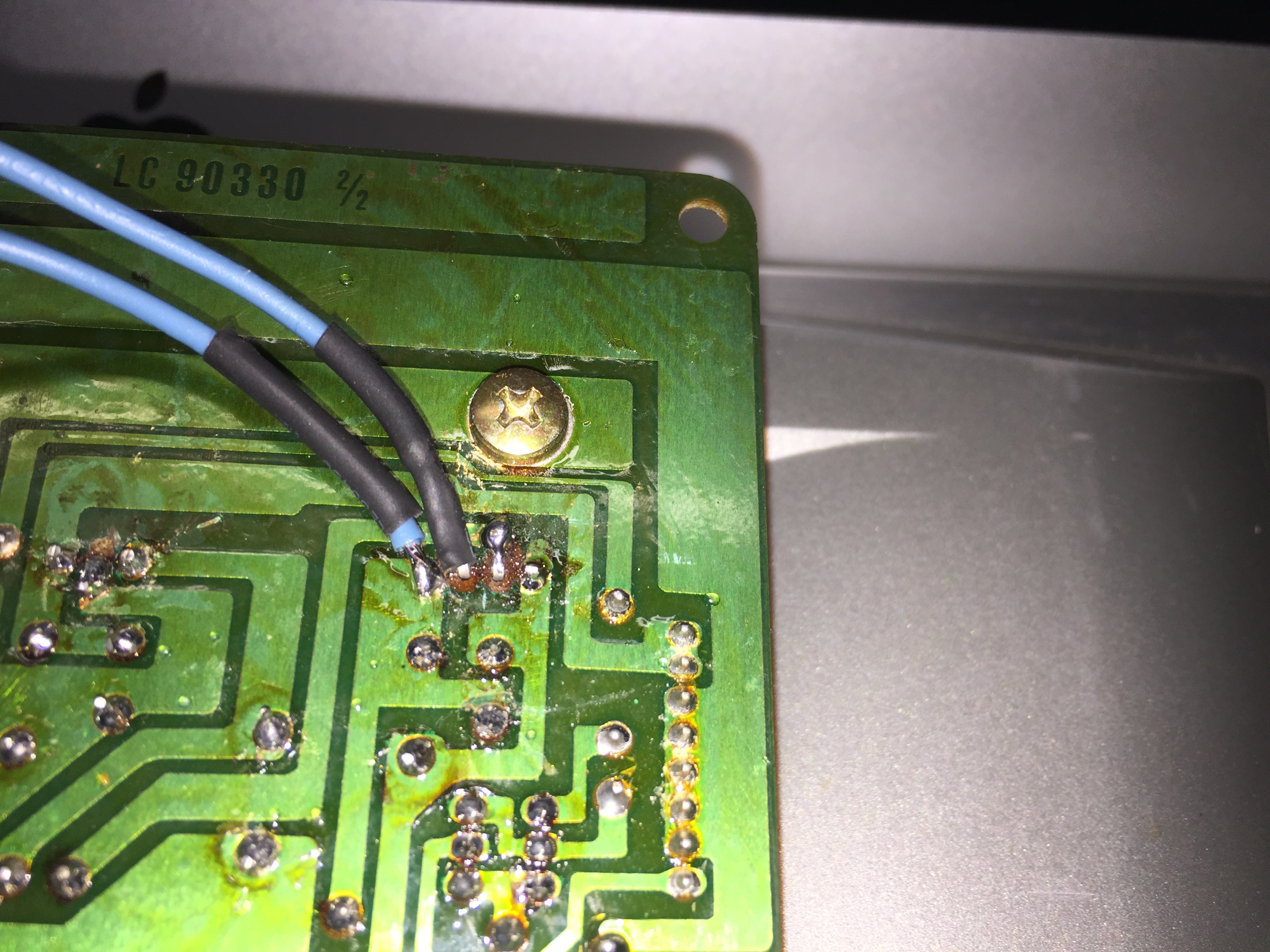
I now put a 7924 before the 7915 to get the voltage down to 24 and them feed it into the last 7915 to get -15V
in the pictures you can see what I did.
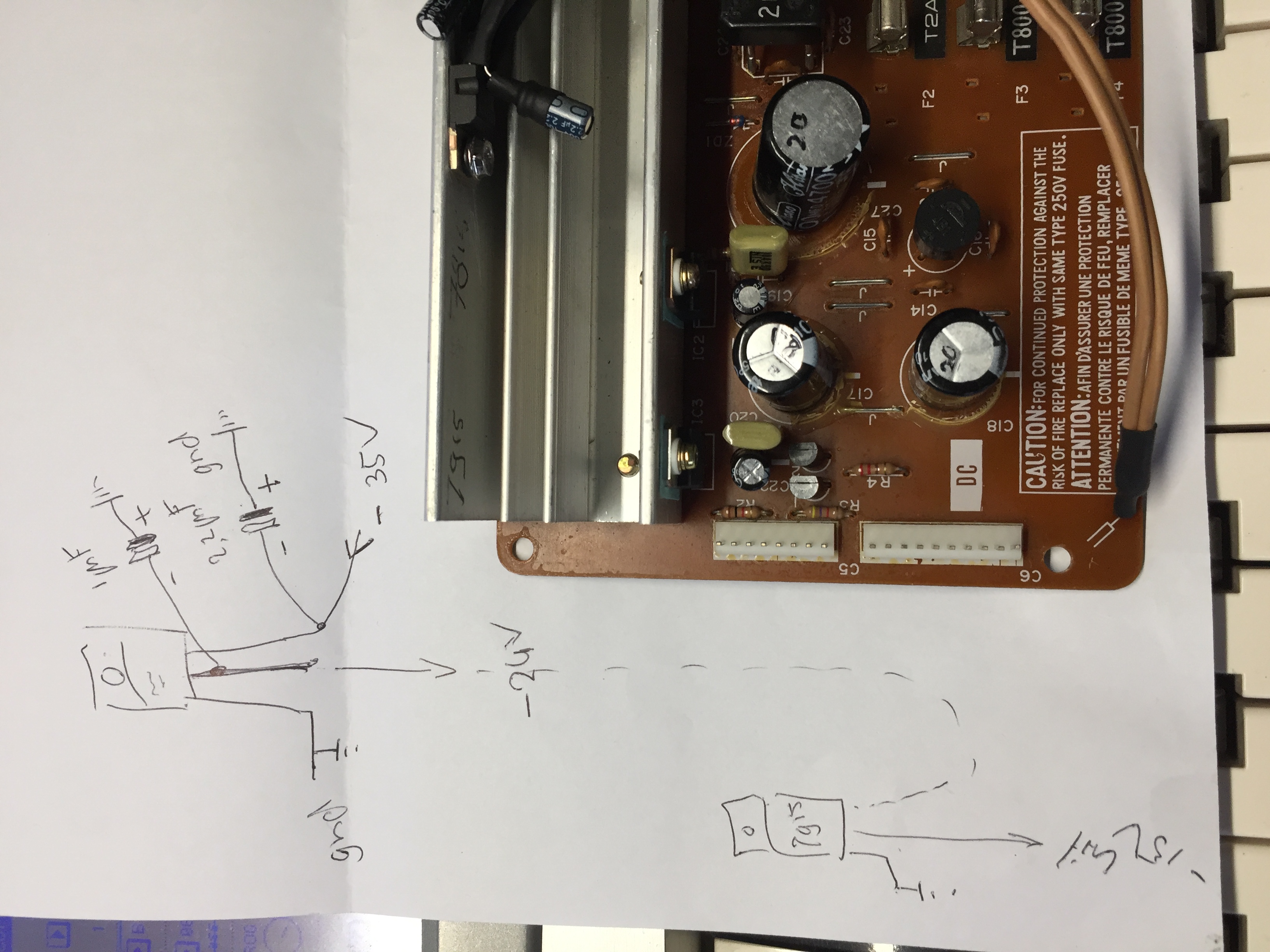

so far so good the output voltage is now -14.8V close enough I guess and definitely better then the -25 I had.
I’m just a little afraid to put it in again…
Hey everyone, I put in the board again and now I am getting a decent output on the level you would expect from a line output.
I do however still get the distorted sound.
What’s the next step? how do I go about fixing that?
https://www.dropbox.com/s/766kneb8plr4eeg/Testoutput%20DX7%20el%20piano%2025-5-2020.mp3?dl=0
The DX7 has been on for 4 or 5 hours, but the heatsink gets extremely hot.
it seem to be too small for yet another regulator.
I get some weird LCD effect too.
when I select sound 1 it is fine, but it slowly becomes dim.
when I select a sound from the lower row (17-32) it is not readable.
I hear some electric buzz (sound like a short) but can’t find the location.
nu funny smell no sparks nothing.
hmmm…
@wernersaurus, @genesis, @PPD,
are you still here?
Sorry I don’t want to be pushy, but I was hoping someone can help me…

sorry, I’ve got no mail notification for your answers until today ^ ^
I’m pretty sure something is wrong in the electronic side of the synth and this cause a high currant drain thus a high power dissipation.
check if an IC is not very hot when turned on.
I’m using a Flir IR camera for such test but I think you don’t have one 
no I don’t have such a cam, but I can check with my fingers…
any idea’s as what is causing the display to fail?
perhaps the current consumption on the 5V. I hope there nothing dying on the digital side.
Steven:
Adding the additional regulator on the heat sink is possibly raising the temperature too high affecting the other voltage regulators. The 5V tolerance is about 4.75V to 5.25V. Anything outside those values will cause unpredictable behavior for the digital circuits. What is the 5V reading when the display dims?
The distorted sound could be coming from a damaged op-amp when the -15 voltage regulator failed.
Pat
the 5Volts output was fine luckily. but I should test it with load on it.
if an opamp was damaged, that is repairable! hope it is something like that and not one of the Yamaha-chips…
is there a way for me to test that? (before I randomly start swapping out opamps)
desoldering is no problem, I have gotten a lot more confident soldering and desoldering
I would first make sure that the +5V is stable with the load connected. The display should not dim if the +5V is stable. Have you found the source of the buzzing sound?
Once you’re satisfied that the +5V is ok i would replace the following op-amps. IC 54, 55, 57 and 43.
These IC’s have a max. voltage rating of + and - 18V. They were probably damaged when the voltage regulator failed applying -27V to the IC’s.
Also IC 1 on the aftertouch board should also be replaced.
I would highly recommend you install sockets for the IC’s.
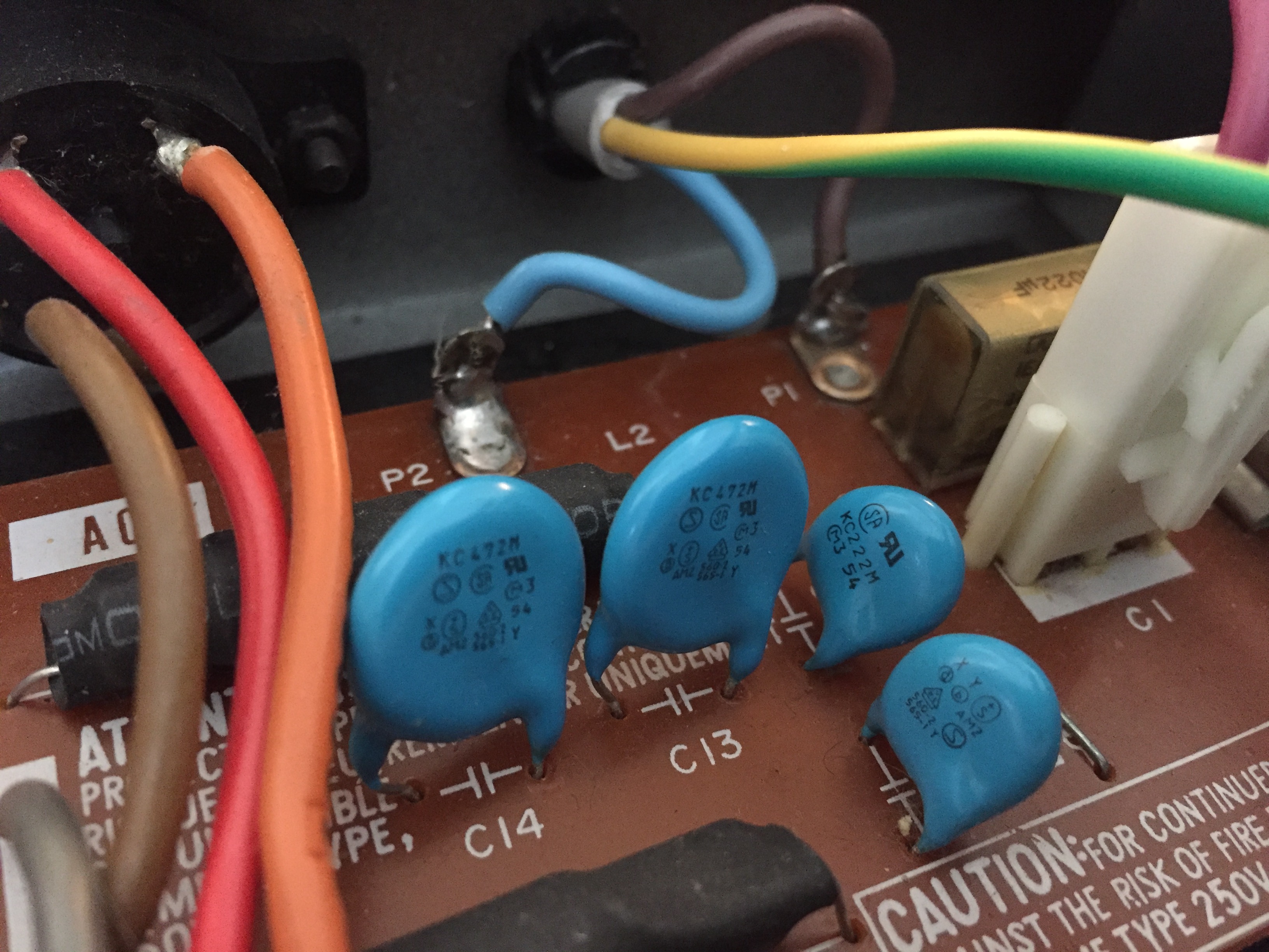
One other thing to check is the capacitor across the power switch. It has been known to fail. Do a visual inspection and check for cracks in the body. It is a special Y-Rated safety capacitor so an ordinary capacitor should not be used.
Pat
2 Likes
thank you I’ll try and get the parts, and will come back to report here
the safety-capacitors look fine to my eye
I had to adjust the voltage a little, it was giving out 4,7V after the adjustment it was 5V but the display was still dim

I get from 1 problem to the next, I am very grateful for all the help I get here!
but I am also wondering if it is still worth all the trouble… I hope it is…
my goal is to get a fully functional DX7 with new OLED display. I was also planning on making DIY wooden side-panels and a XLR balanced output.
this was the reason I openend up the DX7 in the first place, but as long as it doesn’t play that would be a waste of course.
please, somebody tell me it will be ok (I know some of you warned me it would be a long haul…)
The capacitor you want is the rectangular unit beside the (C1) connector. It looks to be a .022 uf unit from the picture. Same value as the North American units.
There appears to be a contrast adjustment pot on the main board (VR1). It’s beside the connector that goes to the LCD display. Did the display dim just recently or was it always like that?
Did you locate the source of the buzz?
Hello again,
The LCD was fine before I started working on the DX7
it was only after I started my trouble with the power supply.
The buzz has not returned since, but mainly because I have the unit off most of the time to prevent it from damage.
I’m not sure what the capacitor is supposed to look like, but there are some cracks in the plastic
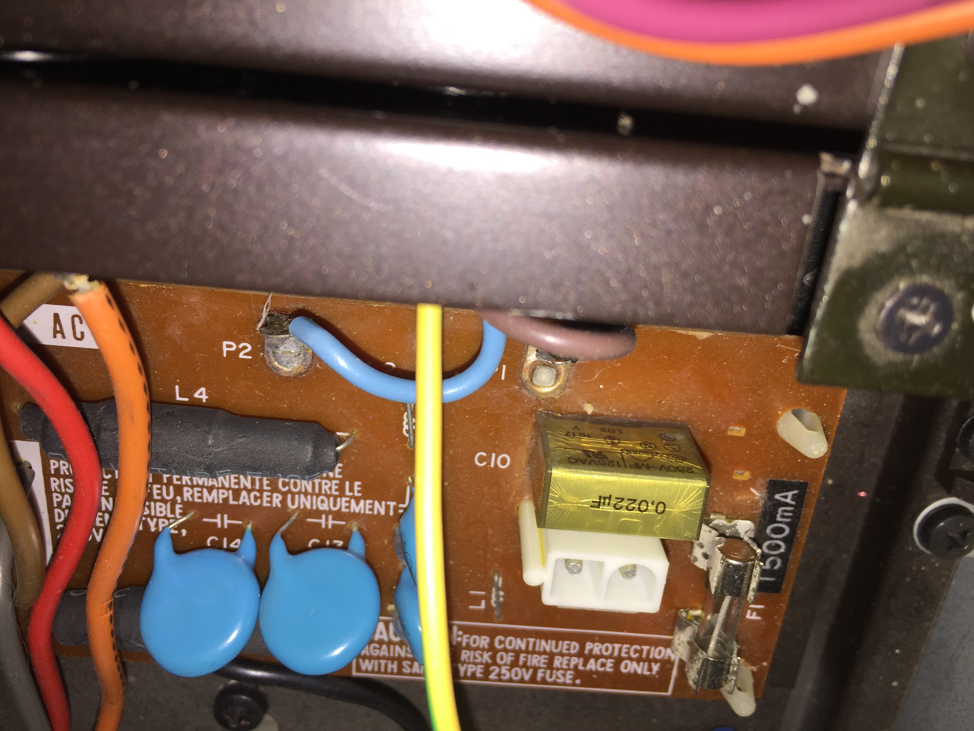
If the capacitor is cracked then it needs replacing. Moisture can get in and the capacitor will fail with a lot of smoke. It’s important to get the information off the capacitor so a suitable replacement can be ordered.
I reviewed the readings you took on the secondary AC voltages of the transformer. They seem a little high which may have affected the -15v regulator.
The secondary AC voltage on your unit was 50 VAC. I measured my unit and it was approx. 45 VAC.
If you’re comfortable reading the AC voltage coming into the unit, it can be measured at the P1 and P2 terminals on the AC board. Please use extreme caution as these terminals are exposed with what should be 240 VAC. If you’re not comfortable taking the reading have someone else take them.
Another item i would check is the voltage selector switch wiring. The schematic shows the wiring of the voltage selector switch. Only the P terminal (brown) and the number 3 terminal (red) should be connected together. The number 2 terminal (orange) should not be connected to anything.
I have kept out of the conversation after others started to contribute - too many cooks!!!
However - reading the above your problem is way more fundamental. No engineer and specifically not professional YAMAHA engineers would design something that close to any tolerance limits. The filter caps after the bridge are 1000uF/35V and you apparently are measuring 34V - that is way too tight … look at that first and foremost.
DX7’s have been around for over 30 years and if this would be an issue it would have been detected and rectified 30 years ago.
What mains are you working off - 110V, 120V, 220V or 240V ??
Hi Werner,
I have 230V ac here (Netherlands)
Thank you for joining in on the conversation again.
fixing the high output before the bridge would mean changing the trafo.
but this is a specific trafo with multiple outputs, it is not easy to find one, I think.
anyway, I did do a workaround as you can see in the above posts.
today I am changing the opamps
I will go ahead and change the bridge as well and see if that makes any difference.