Hey Steven,
I happened across this forum thread on an image search, read the whole thing, and wondered if you ever got it resolved.
As for anyone that would criticize your attempts at fixing your own equipment, I’d tell them to go pound salt and continue learning. What a bonehead thing to do on a FORUM where people go to seek others’ HELP.
Power supplies like this aren’t rocket science, and I’m sure, at the very least, you can plug away and figure out what the issue is. Whether it is beyond fixing (custom chips, etc.) is another thing altogether, but in either case, it is satisfying to see anything like this to the bitter end, so long as you don’t mind the investment in time and parts.
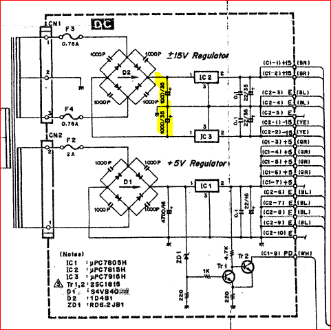
In most consumer equipment (I am not familiar at all with this piece of equipment, full disclaimer, but it’s all the same in the power supply area), you have your line voltage (fused of course), it is switched on through a transformer primary, typically stepped-down to one or more secondaries, and then half- or full-wave rectified, at which point it is smoothed out and further regulated - typically by linear regulators (such as this), or pre-regulated with more efficient means in newer equipment.
After reading casually this entire thread, my gut reaction is that the line voltage is producing too high unregulated voltages for the linear regulators. The electrolytic replacement was a good start, they’re notoriously garbage after years and years of use and abuse. They fail either as an open, a short, or somewhere in between, all while suffering from their usual terrible tolerances. Great for low-frequency filtering, but that’s pretty much it.
Here’s what I’d suggest (I kept thinking of steps  ):
):
-1. If you source your parts from China, Amazon, or eBay, or anywhere else in order to get a “good deal” redo all the work with parts from reputable sources. I have been in a Chinese factory and have seen under THEIR OWN X-ray machine that EVEN THE CHINESE are susceptible to fake parts of all kinds…specifically talking regulators in your case.
-
Take one of your spare -15V regulators and apply voltage from a power supply, and see if it acts weird with overvoltage. If so, then that explains that. I’d also double-check that it is in the board correctly…but there is probably only one way to put it in if it’s on a heat sink. If it were me, I’d look at board traces and confirm in is in, out is out, and ground is ground, but I think you may have done that already. I doubt this is the problem. After testing THAT regulator, put THAT regulator INTO the synth.
-
Disconnect the brain board and using your Variac, and with a meter, turn the voltage up until you get to around 28-30V unregulated (after the bridge rectifiers and before the linear 7815/7915 regulators). Should be just under what your line voltage is, maybe in the 195-205 VAC range if your line is 230 VAC. At this point, your regulators should read proper values. NOTE: My guess is that overcurrent downstream on the -15V rail keeps frying your 7915. They’re robust, but in my experience not as robust as +15V 7815’s, for whatever reason. Anyway, hopefully the voltages are right at this point.
-
If the -15V is still being a pain, and you’re using known-good parts from a good source, try loading it with a 1K resistor. From your experiments above it sounded like the -15V regulator needed some load on its output “reads -15V with the board connected”, though this should not be the case. I agree with everyone that this is very odd; not much to see here, voltage in, -15V out…but…it isn’t…or wasn’t…very weird.
-
At this point, I’m going to take the liberty to assume the regulators are outputting the proper values. Knowing that the 7815, 7915, and 7805’s are good for an amp (but I wouldn’t use them for over 3/4 A myself), we can do this experiment.
3a. With a variable power supply and the ability to limit current output, turn the current knob to minimum and tune the supply to +5V and hook it up to the +5V rail on an UNPLUGGED and UNPOWERED synth board. Slowly begin turning the current knob up to allow more current out. If you have to keep turning the current knob to get to +5V and you get close to 1A when doing so (which would imply you still haven’t reached +5V), do not exceed 1A. Something may be bad on the +5V rail.
3b. Repeat 3a with +15V rail.
3c. Repeat 3a with -15V rail.
-
My bet is that you either find something drawing excess current (spraying 70% isopropyl alcohol on everything and seeing which chip evaporates it off first is a poor man’s FLIR, and better than burning your finger), or something was damaged partially in the past by that high rail on -15V.
-
Or, after you get the right regulator voltages with the Variac technique, everything runs happily and there isn’t distortion anymore. That would be awesome!
-
At one point, I noticed that you had an image of the synth powered on and the LCD screen was visible. I noticed the first line of characters were all black squares, and the bottom was blank. If the board was in the system at that time, and you were doing a test run, that means the microcontroller is not running or is dead. Character LCDs default to first row all black squares, second row all blank, until they are initialized and are directed to display something by a microcontroller.
I hope this all made sense for you or for someone else that sees this post, and hopefully you haven’t thrown in the towel just yet. I’m sure we can get to the point where we at least know what the problem is, which would be cool.
Best regards,
Paul (Dallas, TX)